
Technical Approach to the Grid Blackout
Minimizing the likelihood of blackouts is of the highest importance due to the significant effects that would result from partial or total blackouts in highly industrialized nations. Additional difficulties have been and will be posed by the growing use of renewable energy sources and the system’s geographic expansion through its integration of neighboring nations.
 Why do power grid crashes and total blackouts happen?
The system will be operated closer to its limitations with fewer safety margins as a natural result of this development. If events occur that do not meet the design criteria, the system’s security will be even more compromised.
These facts became evident during the recent incidents in the interconnected system in Spain, Portugal and France in April 2025.
In light of this, it’s clear that protections against catastrophic events must be put in place and coordinated so that the power system and its consumers are not excessively affected.
Nevertheless, in addition to these plausible scenarios, a power system might potentially undergo more disruptive events as a result of many outages occurring at the same time. Such disruptions, depending on the state of the system, have the potential to cause an emergency situation with far-reaching effects.
Certain precautions must be taken to ensure that the electrical system remains stable and free from domino consequences, such as a partial or complete blackout, in the event that such a catastrophe were to occur.
Each country or TSO is responsible for developing and maintaining its own defense strategy. These plans incorporate a set of procedures, most of which are automated, to guarantee a rapid response to major disruptions and to limit their propagation to the smallest available network.
Furthermore, in order to prevent the electrical system from evolving uncontrollably, it is crucial to ensure the safe operation of the protection of the transmission lines or transformers during a severe disturbance.
- How Do We Classify Stability Problems?
- How To Classify Major Power Grid Incidents
- Vulnerability of the Interconnected Power Systems
- Relay Performance During Undervoltage:
- Relay Performance With Dynamic Line Loading:
- BONUS (PDF) 🔗 Download ‘A Guide to Operation and Control of Power Systems With Low Synchronous Inertia’
1. How Do We Classify Stability Problems
When an electric power system is stable, it means that it can recover from a physical disturbance and return to an operating equilibrium condition as soon as possible, with most system variables limited so that the system stays mostly intact, all starting from the same initial operating condition.
For both single and multiple common mode contingencies, most modern power systems can run reliably and safely if the right planning criteria are followed.
In addition, it needs to be resilient enough to withstand several, extremely damaging disturbances, such as transmission line short circuits or the loss of many generators, without undergoing structural modifications as a result of cascade events or the isolation of the faulty components.
Watch Lesson – Introduction To Power System Stability
Appropriate automatic control actions or operator interventions are required because of the velocity of the instability phenomena involved. Considering these factors, a proper categorization of power system stability issues can greatly aid in the understanding of such events and the development of efficient countermeasures:
- The physical nature of the resulting instability;
- The size of the disturbance considered;
- The devices, processes, and time span that must be taken into consideration, in order to judge stability, and
- The most appropriate method of calculation and prediction of stability.
When systems are under a lot of pressure, instability can take many forms, and this is especially true in the case of cascading events and systems that are already failing.
Figure 1 – Classification of power system stability

1.1 Rotor Angle Stability
The stability of the rotor angle is defined as the capacity of synchronous generators in a network to maintain synchronism following a disturbance. The capacity to keep or restore mechanical torque and electromagnetic torque equilibrium throughout the system’s synchronous machines is dependent on the system’s initial operating state.
Potentially unstable behavior includes periodic divergence of the machine’s (or cluster’s) angle from the rest of the system or increased angular swings of select generators, which causes them to become out of sync with other generators.
It is possible to classify issues with rotor angle stability as either small-disturbance or transient stability.
Figure 2 – Transient stability graphs
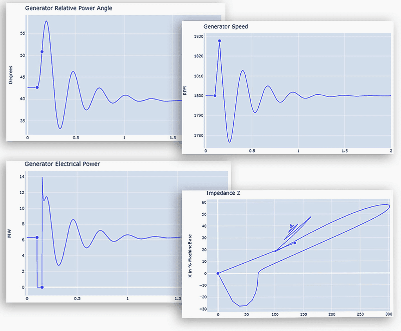
1.1.1 Minor-disturbance (or small-signal) rotor angle stability
A power system is considered stable within this sub-category of instability if it can sustain synchronism even when subjected to minor disruptions. By controlling the magnitude of the disturbances, which are usually white noise, the system equations can be linearized and used for analysis.
Inadequate damping of electromechanical oscillations is typically linked to the stability problem.
Damping decreases if:
- Gain of exciter increases;
- The impedance seen from the plan increases;
- The inertia of the unit is low;
- Produced active power increases;
- The machine is under-excitated.
Minor disruption issues with rotor angle stability might manifest on a local or global:
Local issues: In most cases, a single power plant’s rotor oscillations versus the rest of the power system [0.8 → 2 Hz] are the cause of local difficulties, which affect a limited portion of the power system. It is the local plant mode oscillations that cause these fluctuations.
Global issues: When large numbers of generators interact, it can lead to global problems that impact a vast area. In them, one set of generators oscillates in opposition to another set of generators in a different area. These variations, which range from 0.2 Hz to 0.8 Hz, are known as inter-area mode oscillations.
For small signal rotor angle stability, the time range of interest is approximately 10 to 20 seconds after a disruption.
Watch Lesson – Small Disturbance Stability Equation – Synchronizing Power
1.1.2 Large-disturbance rotor angle stability or transient stability
The capacity of the generators to remain synchronized following a significant disruption, like a bus or transmission line short circuit, is called transient rotor angle stability. First swing instability, caused by an inadequate synchronizing torque, typically appears as aperiodic angular separation.
It is common practice to identify a group of generators powered by a single machine in large production poles. Similar occurrences can be compared to:
- Adopting valving protection quickly;
- Deactivating the “dominant cluster generator” to reduce local acceleration as an extreme measure
Both forms of rotor angle stability are considered to be events with a relatively short duration, as illustrated in Figure 1.
Watch Lesson – Large Disturbance Stability OR Equal Area Criterion
1.2 Frequency Stability
Frequency stability refers to a power system’s capacity to achieve and keep a stable operating point (viable from generators) after a substantial disturbance (causing a considerable imbalance between production and consumption). Instability may manifest as prolonged frequency fluctuations, resulting in the tripping of producing units and/or loads, or as an aperiodic transient.
In extensive interconnected power systems, this scenario is predominantly interconnected to instances after the division of systems into islands. In this context, stability refers to the ability of each island to attain a state of stable operational equilibrium with minimal accidental load loss.
The overall response of the island, as indicated by its mean frequency, determines it, rather than the relative motion of machines.
Frequency stability problems are associated with:
- Inadequacies in regulation/control of power plants;
- Poor coordination of control and protection equipment;
- Intempestive protection trips leading to islands or high load-generation;
- Imbalance;
- Out of step of power plants;
- Voltage instability;
- Insufficient generation reserve, respectively excessive load imbalance.
Related electrical guides & articles


Edvard Csanyi
Hi, I'm an electrical engineer, programmer and founder of EEP - Electrical Engineering Portal. I worked twelve years at Schneider Electric in the position of technical support for low- and medium-voltage projects and the design of busbar trunking systems.I'm highly specialized in the design of LV/MV switchgear and low-voltage, high-power busbar trunking (<6300A) in substations, commercial buildings and industry facilities. I'm also a professional in AutoCAD programming.
Profile: Edvard Csanyi
