
Preventing specification mistakes
To be honest, a circuit breaker is fairly simple device. However, the process of specifying circuit protection is often complicated and unclear, leading many engineers to either include insufficient or excessive protection in their equipment designs. Insufficiently protected circuits expose equipment to potentially harmful electrical surges.
 Twelve ultimate mistakes when selecting circuit protection for low-voltage equipment
Excessive protection of circuits incurs additional expenses and may result in frequent and unnecessary circuit interruptions. Similar to the famous story of Goldilocks and the three bears, the objective is to determine the optimal circuit protection that is perfectly suitable.
This technical article aims to provide invaluable assistance to numerous engineers in navigating the specification process. Throughout the years, I’ve come across numerous misunderstandings, and I have chosen the twelve most prevalent screw ups for this technical article.
The aim of this article is to prevent these mistakes and safeguard your designs with optimal circuit protection by providing our knowledge and experience.
- Picking the Wrong Type of LV Circuit Breaker
- Specifying a High CB Rating to Avoid In-Rush or Transient Current Tripping
- Lack of Circuit Breaker Spacing In the Design
- Over Specifying IP Protection Degree
- Selection of the Non Suitable Actuation
- Not Considering Using Breaker as On/Off Switch
- Specifying the Wrong Type of Terminal
- Specifying a Fuse When a Circuit Breaker Would be Better
- Selecting the Improper Circuit Breaker for Extreme Vibration
- Forgetting to Derate a Circuit Breaker
- Derating a Breaker When It’s Not Necessary
- Over Specifying a Breaker Interrupting Capacity
- Final Words
- BONUS! Download Handbook: Electrical Installation Designs (PDF)
1. Picking the wrong type of LV circuit breaker
Or good breaker type for wrong application…
The mistake most commonly made by design engineers is the selection of an inappropriate circuit breaker technology for a certain application. There are four options available for circuit breaker technology: thermal, magnetic, thermal-magnetic, and high performance. Each technology has a unique trip profile in terms of time and current, and each includes specific mechanical features.
Magnetic circuit breakers function through the use of a solenoid, promptly triggering a trip once the threshold current has been attained. This kind is suitable for use in printed circuit board (PCB) applications and for quickly disconnecting impulses in control applications.
Derating may be necessary if the object is installed in a non-horizontal orientation.
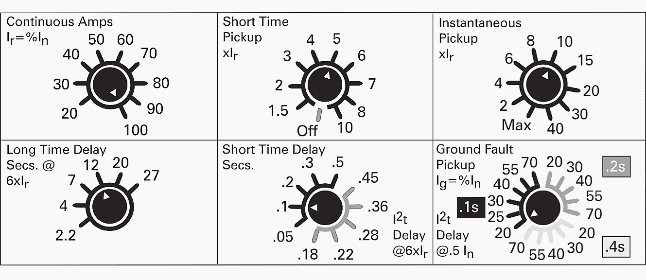
Figure 1 – Circuit breaker adjustable tripping functions
Breakers utilize a heat-sensitive bimetal strip or disk. This kind provides a gradual characteristic curve that distinguishes between short-lived, harmless power spikes and extended periods of excessive demand. This is suitable for machines or vehicles that experience strong current surges when electric motors, transformers, and solenoids are started.
Thermal-magnetic circuit breakers offer the advantages of both thermal and magnetic circuit breakers. They have a delay mechanism that prevents unnecessary tripping due to typical inrush current, while also providing a quick response to large currents.
The solenoid is swiftly activated by high levels of current, whereas the thermal mechanism is designed to respond to extended periods of low-value overloads. Their trip profile follows a distinct two-step pattern, which efficiently safeguards valuable electrical systems from short-circuits while decreasing the chances of system disruption.
Thermal circuit breakers designed for high performance applications use a compensating device that eliminates the influence of ambient temperature on their sensitivity. A significant number of engineers rely on the support desks of circuit breaker manufacturers for specification assistance.
Nevertheless, exercise caution when considering recommendations from firms specializing exclusively in a single variety of circuit breaker.
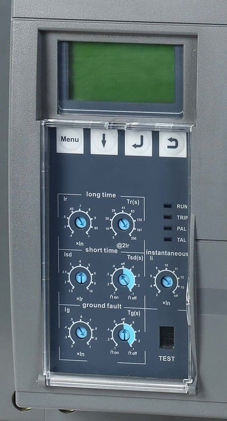
Figure 2 – LV circuit breaker protection settings
2. Specifying a High CB Rating to Avoid In-rush or Transient Current Tripping
No need to oversize a circuit breaker…
Engineers typically design circuit breakers with significantly higher ratings than necessary, despite the fact that nuisance tripping is a legitimate problem. A contributing factor is the common misunderstanding of fuses and circuit breakers. In order to avoid nuisance pinching, engineers typically oversize the fuses.
Having said that, a circuit breaker of an excessive size is unnecessary. Instead of telling you the maximum current that a fuse can handle at room temperature, a circuit breaker’s rating will tell you that same maximum current continuously.
Under such circumstances, the designer must designate a circuit breaker with a time delay. Thermal circuit breakers inherently possess a built-in delay, but magnetic circuit breakers can potentially have additional delays due to hydraulic mechanisms. Align the delay with the duration of the anticipated in-rush currents.
Figure 3 – Schneider Electric’s Compact NSX circuit breaker rating plate
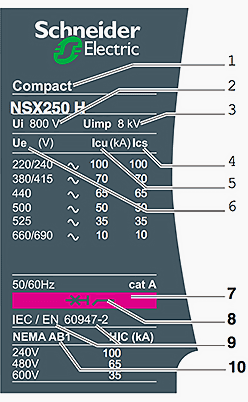
Where:
- Type of device – frame size and breaking capacity class
- Ui – rated insulation voltage.
- Uimp – rated impulse withstand voltage.
- Ics – service breaking capacity.
- Icu – ultimate breaking capacity for various values of the rated operational voltage Ue
- Ue – operational voltage.
- Colour label – indicating the breaking capacity class.
- Circuit breaker-disconnector symbol.
- Reference standard.
- Main standards with which the device complies.
3. Lack of Circuit Breaker Spacing in the Design
Heating as the huge problem…
Adhering to the stated minimum separation requirements between non-temperature-compensated thermal circuit breakers is crucial.
Only a 1 mm gap between breakers is necessary. In the absence of this little thermal gap, the circuit breakers may experience excessive heating, leading to an elevation in the sensitivity of the bimetal trip mechanism. To ensure that the breakers make contact with each other, reduce their amperage rating to 80% of their normal value.
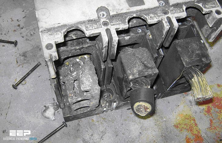
Figure 4 – Damaged circuit breaker feeding a capacitor bank. A thermal examination detected abnormal heating due to not enough space around breaker
4. Over specifying IP Protection Degree
Don’t do it, it’s expensive and stupid…
The ubiquitous use of terms like drip-proof, ignition-proof, water splash-proof, and dustproof can lead to misunderstandings if not defined consistently. For example, when defining the degree of protection of electrical equipment, use the standards that have already been created, such as standard IEC 60529.
Determine the most appropriate level of security for the task at hand by consulting these guidelines. For instance, a breaker with ignition protection would be useful in a boat’s engine room but superfluous in the boat’s panel.
The degree of protection offered by such an enclosure is indicated by an index of protection (IP) code, as shown in Table 1 and 2 below.
Table 1 – Index of protection (IP) code: First digit – Mechanical protection
| No. | Description |
| 0 | No protection of persons against contact with live or moving parts inside the enclosure. No protection of equipment against ingress of solid foreign bodies. |
| 1 | Protection against accidental or inadvertent contact with live or moving parts inside the enclosure by a large surface of the human body, e.g. a hand, but not protection against deliberate access to such parts. Protection against ingress of large solid foreign bodies. |
| 2 | Protection against contact with live or moving parts inside the enclosure by fingers. Protection against ingress of medium-size solid foreign bodies (12.5 mm spheres). |
| 3 | Protection against contact with live or moving parts inside the enclosure by tools, wires or such objects of thickness greater than 2.5 mm. Protection against ingress of small foreign bodies. |
| 4 | Protection against contact with live or moving parts inside the enclosure by tools, wires or such objects of thickness greater than 1 mm. Protection against ingress of small solid foreign bodies. |
| 5 | Complete protection against contact with live or moving parts inside the enclosure. Protection against harmful deposits of dust. The ingress of dust is not totally prevented, but dust cannot enter in an amount sufficient to interfere with satisfactory operation of the equipment enclosed. |
| 6 | Complete protection against contact with live or moving parts inside the enclosures. Protection against ingress of dust. |
Table 2 – Index of protection (IP) code: Second digit – Liquid (water) protection
| No. | Description |
| 0 | No protection. |
| 1 | Protection against drops of condensed water. Drops of condensed water falling on the enclosure shall have no harmful effect. |
| 2 | Protection against drops of liquid. Drops of falling liquid shall have no harmful effect when the enclosure is tilted at any angle up to 15° from the vertical. |
| 3 | Protection against rain. Water falling in rain at an angle equal to or smaller than 60° with respect to the vertical shall have no harmful effect. |
| 4 | Protection against splashing. Liquid splashed from any direction shall have no harmful effect. |
| 5 | Protection against water jets. Water projected by a nozzle from any direction under stated conditions shall have no harmful effect. |
| 6 | Protection against conditions on ships’ decks (deck with water-tight equipment). Water from heavy seas shall not enter the enclosures under prescribed conditions. |
| 7 | Protection against immersion in water. It must not be possible for water to enter the enclosure under stated conditions of pressure and time. |
| 8 | Protection against indefinite immersion in water under specified pressure. It must not be possible for water to enter the enclosure. |
| X | Indicates no specified protection. |
It will be seen from Table 1 that, for instance, an enclosure to IP 56 is dustproof and waterproof.
Suggested Video – What is IP Rating? IP Rating Explained
5. Selection of the Non Suitable Actuation
Always have the CB application on your mind…
Resetting circuit breakers requires the use of an actuator, which is done manually. Actuators come in a wide variety of configurations, such as press-to-reset, push-pull, push-push, rocker, toggle, baton, and press-to-reset with manual release. Consideration of the actuator type is more than just a matter of aesthetics.
In the case of important applications, for instance, push-pull style actuators are typically required since they are the most resistant to inadvertent actuation.
Figure 5 – Air-circuit breaker (ACB) with busbar coupling in LV switchgear assembly

6. Not Considering Using Breaker as On/Off Switch
Never forget to optimize your protection design…
In many cases, circuit breakers are designed to function as both a switch and a breaker at the same time. The advantages of a combination device include a reduction in the number of components, a decreasing use of panel space, a reduction in the amount of wire, and an increase in protection in comparison to conventional switches.
Figure 6 – LV circuit breaker with protection settings

7. Specifying the Wrong Type of Terminal
The most common mistake…
Circuit breakers that have fast-connect terminals that are similar to plug-in-style terminals make installation and replacement more simpler (they can also be soldered). Connections made using screw terminals are more secure and are particularly well-suited for settings with high current and significant vibration.
It is feasible to use quick connect terminals for circuit breakers with a maximum current rating of 25A.
Good Reading – A roadmap for engineers seeking mastery in the language of electrical schematics
A roadmap for engineers seeking mastery in the language of electrical schematics
8. Specifying a Fuse When a Circuit Breaker Would Be Better
Fundamental lack of knowledge of topology…
Despite the fact that fuses offer low-cost protection for circuits, the cost reductions should be balanced against the low total cost of ownership that circuit breakers have. In the first place, circuit breakers may be reset in a short amount of time, which makes it possible to restore the circuit with a minimum amount of downtime.
Furthermore, there is no guarantee that a replacement fuse will have the appropriate rating after it has been installed.
There is the possibility of adding an auxiliary contact that is capable of transmitting an alarm condition to an LED indicator or to software that processes data. In addition, a switch and a circuit breaker can be attached together, which not only saves space but also provides safety against overloading. There is also the possibility of a remote trip, which is only accessible with circuit breakers and not with fuses.
Furthermore, in contrast to fuses, circuit breakers come in a wide range of types and trip types, which allows them to be more accurately tailored to the loads and environment on which they are installed. Lastly, it is impossible to test fuses without causing them to be blown (destroyed).
On the off chance that there is an overload, how can you be certain that the fuse you designate will open?
Recommended Reading – Failure cases of LV/MV electrical equipment and what should have been done (to avoid them)
Failure cases of LV/MV electrical equipment and what should have been done (to avoid them)
9. Selecting the Improper Circuit Breaker for Extreme Vibration
Tough environment needs tough breaker…
Usually, a magnetic circuit breaker is activated by a pivoting metal armature that shuts in reaction to the motion of a magnetic coil. The susceptibility of magnetic circuit breakers (including magnetic-hydraulic circuit breakers) to vibration renders them especially prone to premature closure of the armature.
On the other hand, a conventional thermal circuit breaker consists of a heat actuator and a mechanical latch.
Thermal circuit breakers provide a high level of resilience to stress and vibration. By employing a push-pull style actuator, the vibration resistance of a magnetic circuit breaker, if deemed the most suitable option for the given application, can be enhanced. This actuator possesses a latching construction.
10. Forgetting to Derate a Circuit Breaker
A rule of thumb often forgotten…
Typically, the circuit breaker should have a rating that is equal to 1 percent of the load’s power. Nevertheless, certain applications necessitate the uninterrupted operation of a circuit breaker under extreme high or low temperatures. In such instances, adhere to the manufacturer’s instructions for reducing the rated capacity.
For instance, if an application necessitates 10A protection, it would require a thermal circuit breaker with a rating of 12A when operated at a temperature of 50 degrees Celsius.
Suggested Study – Calculation of short-circuit withstand current rating for low voltage switchgear
Calculation of short-circuit withstand current rating for low voltage switchgear
11. Derating a Breaker When It’s Not Necessary
A rule of thumb often over used…
Thermal circuit breakers are responsive to variations in the surrounding temperature. In a cold environment, the circuit breaker will trip at higher amperage, while in a hot climate, it will trip at lower amperage. An error often made is assuming that derating is required for thermal circuit breakers in circumstances where there are increases in ambient temperature. Wrong.
The performance of a thermal circuit breaker is directly influenced by the performance requirements of the system, provided that it is subjected to the same heat source.
There is another mistaken belief that magnetic-hydraulic style circuit breakers are not affected by changes in performance when the surrounding temperature increases.
In contrast, these circuit breakers are equipped with a dashpot that contains a liquid core. This liquid core exhibits increased fluidity as the temperature rises, hence decreasing the duration of the hydraulic delay.
Highly Suggested – A practical handbook for low- and high-voltage switchboards
12. Over Specifying a Breaker Interrupting Capacity
Very common mistake, just in case…
The interrupting capacity refers to the highest current that a circuit breaker can safely interrupt. Circuit breaker manufacturers provide this specification in conjunction with the circuit breaker’s operational capacity. Typically, manufacturers provide two sorts of specifications for interrupting capacity.
The first one is referred to as Icn, or Normal Interrupting Capacity. The Icn is the maximum current that the circuit breaker can repeatedly interrupt, with a minimum of three times, according to the IEC 60934 standard. The lcn function provides an approximate indication of the quality of a circuit breaker.
Another requirement is the UL1077 Interrupting Capacity. UL1077 (or IEC 60934) specifies the maximum current that a circuit breaker can safely interrupt at least once without posing a risk of fire. In order to adhere to different regulations, engineers are required to designate circuit breakers with sufficient interrupting capacity.
Regrettably, the process of adopting the correct standard may be perplexing. UL 489 mandates an interrupting capacity of 5000A or more.
Although this standard is suitable for main power distribution purposes, it has been adopted in other industries where the short circuit rating, determined by circuit resistance, is significantly lower.
The telecommunications business is highly susceptible to over specifying interrupting capacity due to the fact that certain vendors of circuit breakers for DC telecom equipment also promote these circuit breakers for AC power distribution. Despite the seemingly abundant supply of current in telecom applications, the actual quantity of current available is significantly reduced due to line loss.
A circuit breaker with a 2000A interrupting capacity is sufficient for the majority of telecommunications applications.
Useful Sheet – Short circuit current calculation at various point of electrical circuits (Isc)
Short circuit current calculation at various point of electrical circuits (Isc)
13. Final Words
If you keep these suggestions in mind, it will be simple for you to precisely determine the appropriate level of circuit protection at the most economical price. Begin the process of selecting by making an effort to achieve a comprehensive understanding of your burden.
The next step is to choose which kind of circuit breaker is most appropriate for the application you are using.
By avoiding the typical errors that occur during the specification process, you will be rewarded with a design that is dependable.
14. BONUS! Download Handbook: Electrical Installation Designs (PDF)
Download BONUS: Download handbook ‘Electrical Installation Designs’ (223 pages, PDF) (for premium members only):
Related electrical guides & articles


Edvard Csanyi
Hi, I'm an electrical engineer, programmer and founder of EEP - Electrical Engineering Portal. I worked twelve years at Schneider Electric in the position of technical support for low- and medium-voltage projects and the design of busbar trunking systems.I'm highly specialized in the design of LV/MV switchgear and low-voltage, high-power busbar trunking (<6300A) in substations, commercial buildings and industry facilities. I'm also a professional in AutoCAD programming.
Profile: Edvard Csanyi

I’m from Papua New Guinea. I’m an Industrial Electrician. Interested in your
Electrician literatures and ideas put forth on your pages.
Dear sir,we are a panel builder company in Iran with 35 years experience.Because of some problems ,many workforce immigrated to out of country and we are in need of workforce .Could you introduce some expert people for job vacancy in Iran?