
Transformers In a Power Plant
This technical article provides an overview of the various choices and assists electrical engineers in determining the criteria that should be included in the transformer specifications in order to meet the requirements of their particular application. A power plant often includes several essential equipment such as transformers, high voltage (HV) switches, HV circuit breakers, arresters, and protective panels.
 Transformers in plant power distribution: The bigger picture
Additionally, it has medium voltage (MV) switchgear linked to the low voltage side of the transformers. Specifications for the long lead electrical equipment need to be really promptly drafted. Transformers should be highly prioritized in every power plant.
Large transformers have a significant lead time, typically taking 12 to 18 months for delivery in addition to the procurement process. Transformers having a maximum rating of 10 MVA can be acquired in nine months. Large transformers are often pre-purchased with a cancellation option if the project does not receive approval to proceed.
We require information on plant load, future load, voltages, and cooling method to acquire the transformers.
It is important to note that the lead times that have been provided above are the average lead times that have been taken over the past 10 years, prior to any of the present transport problems occurring.
This article tackles the most common transformer winding configurations and explains phase shifts in power transformers. Essential factors for the correct specification of plant transformers, such as transformer impedance, turns ratio, no-load and load losses, are discussed.
Dry type and oil-type transformers and their differences are reviewed.
- Transformer Winding Configurations:
- Phase Shift in Transformers:
- Tap Changers (On-LTC and Off-LTC)
- Dry and Oil Type Transformers
- Transformer Dielectric Test
- BONUS: Download Transformer Practical Handbook (PDF)
1. Transformer Winding Configurations
A few common arrangements for transformer windings are as follows. For plant distribution, only a select few are utilized:
Star-Delta (Y–Δ)
This is the ideal option for high-voltage grid transformers, as it has a neutral that is properly grounded and a smaller Basic Insulation Level (BIL). In the most recent project that we worked on, the arrangement that was utilized for the primary 275 kV transformers was.
It is also customary to use Yd1.
Figure 1 – Transformer Connection Star-Delta

More information about Star-Delta transformer connection.
Star-Star (Y–y)
This arrangement may or may not be grounded, depending on the circumstances. Due to their poor performance in producing solid grounding conditions, it is not utilized in the power distribution business. This is primarily the reason for this.
Figure 2 – Star-star connection without tertiary winding
More information about Star-Star transformer connection.
Delta-Star (Δ–y)
Delta-Star configuration is usually the best choice for medium-voltage and low-voltage systems: from 3.3–34.5 kV.
Figure 3 – Delta-Star connection
More information about Delta-Star transformer connection.
Delta-Delta (Δ–Δ)
Transformers with Delta-Delta arrangement are rarely used. They are used mostly for special applications.
Figure 4 – Delta-Delta Transformer
More information about Delta-Delta transformer connection.
Autotransformer-Delta (A–Δ)
It’s usually an autotransformer with a Yy tap configuration and a tertiary Δ winding. Utilized for extra high-voltage (EHV) grid connections. The Δ winding provides steady and balanced grounding conditions for both autotransformer voltages.
In addition to stabilizing the neutral points, the Δ tertiary winding can be utilized with capacitors or reactors to regulate voltage on the line.
Suggested Reading – Autotransformer Connection Explained
ZigZag (Zg)
ZigZag configuration is used single winding transformers. They are mostly utilized as a grounding transformer. The Δ winding of a Y–Δ transformer permits the flow of Io currents while producing a flux canceling effect.
Figure 5 – ZigZag transformer coil connections

2. Phase Shift in Transformers
As the primary terminals are connected to the secondary terminals, the Y–Δ or Δ–y transformer generates a natural phase shift of 30 degrees, often known as lead or lag. When the phase sequence is considered to be counterclockwise (CCW), the lead 30° transformer is commonly referred to as the Dy11 transformer. On the other hand, a Dy1 transformer is referred to as having a lag angle of 30 degrees.
Both the primary and secondary phases are considered to be in phase if they are looped around the iron core in the same opposite direction.
In order to lead or lag, it is necessary to shift the phases by one phase. This can be accomplished by following the following sequence: ABC – abc → ABC – cab, or ABC – bac, respectively.
Let us have a look at the transformations that are utilized in a typical power plant, beginning from the top (Grid) and ending at the bottom (415 V services), following the two paths that are depicted on the phasing diagram Figure 6. These transformations pertain to the station services and generator paths.
Figure 6 – Plant phasing diagram

Transformers with two winding designs have been universally accepted by power plants. These configurations are known as 30° lead (11) and 30° lag (1) transformer respectively. In order to keep the angle between the grid (which is supposed to be 0) and the remainder of the station service, the practice is to string the downstream plant transformers in series to move back and forth.
This is done in order to maintain the angle, which can be either +30° or −30°, as demonstrated in Table 1a and 1b, which is an actual scenario for a power plant.
Upon receiving power from the grid via station service transformers (SSTs), the unit services bus on this specific power plant is adjusted by +30° after three grid transformations, operating at 415 V. Both the generating path and the grid can access the same services bus via the auxiliary transformer (UAT) on two transformations.
At startup, the unit (generator) receives its services from SST. The unit load is routinely transferred to the UAT once the voltage reaches 90%. In order to close the UAT, the unit services will be temporarily disabled for less than two seconds. Once the breaker is closed, the drives that were in service are restored to service by the plant control system.
The unit will turn off if the transfer is not completed successfully within four seconds with all the critical starting loads operating.
Table 1a – Phasing diagram of a plant – Path: from grid to 415 V station service
| Transformation | Shift angle | Overall shift | Location | |
| 275 kV grid | Assumed 0 | 0 | 0 | 275 kV grid |
| Ynd1 | 275–33 kV | +30° lead | +30° lead | Local distribution |
| Dyn11 | 33–11 kV | −30° lead | 0 | Plant distribution |
| Dyn1 | 11 kV–415 V | +30° lead | +30° | Plant services |
Table 1b – Phasing diagram of a plant – Path: from grid to generator
| Transformation | Shift angle | Overall shift | Location | |
| 275 kV grid | Assumed 0 | 0 | 0 | 275 kV grid |
| Ynd1 | 13.8–275 kV | +30° lead | +30° | Gen. voltage |
| Dyn11 | 13.8 kV–415 V | −30° lead | 0 | Unit services |
This operating schematic includes two 33 kV transformers that offer local 33 kV distribution to nearby areas. If 33 kV service was not required for these transformers, the two channels might be configured in phase at the 415 V bus, and synchronization could be accomplished by live transfer.
Industrial plants, which operate primarily on the basis of radial distribution, are less likely to encounter such issues.
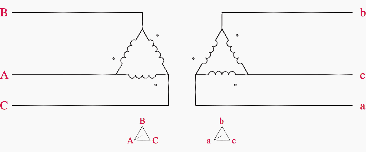
Figure 7 depicts the most frequent arrangements in power and industrial plants, including the Zg grounding transformer. The separate diagrams depict the phasing links. When seen from opposite ends, the transformers at the bottom right exhibit opposing configurations: Dy11 = Yd1, and Dy1 = Yd11.
Figure 7 – Transformer winding configurations

Transformer Impedance
In North America, the impedance is referred to as Z, and it is measured on a per-unit or percentage basis depending on the transformer’s base MVA rating. In Europe, it is referred to as uk%, and the voltage decreases that occur during a short circuit. They are identical in every way.
The transformer base rating, which is the rating of the transformer before it is subjected to forced cooling, is the impedance that must be referred to.
Further Study – How to determine power transformer impedance for calculation of short-circuit currents
How to determine power transformer impedance for calculation of short-circuit currents
Turns Ratio
The turn ratio on normal taps is the same as the voltage ratio for the transformer’s no-load load at the neutral tap. When the transformer is loaded, the voltage ratio no longer equals the turns ratio due to the voltage drop generated by the transformer impedance.
Transformer Losses
Transformer efficiency is high, with large transformers reaching over 99.5%. No-load losses are typically 1:6 versus load losses.
Good Reading (PDF) – A case study of maintenance and condition monitoring of the power transformers
A case study of maintenance and condition monitoring of the power transformers
No-load Losses
No-load losses, commonly known as iron losses, are all losses caused by magnetization at full voltage with the secondary circuit open (not loaded). They are measured while conducting an open circuit test. It includes eddy current losses, hysteresis losses, I2R loss caused by the stimulating current, and dielectric losses.
No-load losses are largely consistent for all transformer loads and proportional to voltage up to the nominal voltage. They increase dramatically in the core saturation zone above nominal voltage.
Good Reading (PDF) – Placement and rating planning of feeders & transformers for LV/MV distribution networks
Placement and rating planning of feeders & transformers for LV/MV distribution networks
Load Losses
Load losses, also known as Cu Losses (or copper losses), are I2R losses generated by the load current flowing through the windings at the rated secondary current. Cu losses fluctuate with the square of the load current and are assessed during a transformer short-circuit test.
Auxiliary Losses
Auxiliary losses are the losses for the auxiliary power used to support the MVA output, such as transformer cooling fans and water pumps, as the loading approaches nominal levels. The auxiliary load for water pumping systems is often less than one-tenth of the no-load loss, and for fan cooling, it is one-twentieth.
Good Guide (PDF) – Distribution transformer guide: Installation, commissioning, operation and maintenance hints
Distribution transformer guide: Installation, commissioning, operation and maintenance hints
Transformer Cooling
Both no-load and load losses in transformers produce heat, which needs to be dissipated to maintain the temperature class and prolong the insulation’s lifespan. Air-cooled transformers achieve cooling by proper ventilation and cooling ducts within the coils. Fans are installed to enhance heat dissipation from magnetic elements and critical dielectric insulating components.
The cooling process for oil-filled transformers is analogous. The cooling ducts in the coils need to be numerous and large enough to facilitate the flow of oil through the coils for heat removal. This fluid can be moved by natural convection, air blowers, or pumped with oil and water. The tank’s surface area must be sufficient to efficiently remove heat from the cooling system using conduction, convection, radiation, and forced cooling, using detachable radiators.
There are several most common designations for transformer cooling, including the following:
Table 1 – The most common designations for transformer cooling
| Designation | Description |
| ONAN | Oil natural air natural. The basic self cooled unit. |
| ONAF | Oil natural air forced. Unit cooled with air fans. |
| OFAF | Oil forced air forced. The unit equipped with oil pumps circulating oil and oil being cooled by external air fans. |
| AN | Dry type transformer cooled by air, naturally. |
| ANAF | Dry type transformer cooled by external fans. |
| OWAF | Oil cooled by means of air cooled water exchangers. This may be the size-saving solution for larger transformers built for limited space locations. |
| ODWF | Oil directed water forced. Similar to OWAF, but the oil is directed through the special channels in the iron ore and next to the coils, then cooled in the water cooled heat exchangers. |
| ONAN/ONAF/ ONAF | Transformer with this cooling configuration has two stages of fan cooling, each rated 33% of the base rating. For a base 20 MVA unit, this would be 20/26.6/33.3 MVA rated transformer. |
Temperature Rise (Insulation Class)
The term “Temperature Rise” refers to the average temperature increase of the windings compared to the surrounding temperature when the transformer is operating at its specified (normal) capacity.
Liquid-filled transformers are available with standard temperature rises of 55 and 65 degrees Celsius. The transformer rated at 55 °C is larger and more expensive. Dry-type transformers come in normal temperature increases of up to 220 °C.
The figures are determined with a maximum ambient temperature of 40 °C. An 80 °C rise dry transformer can reach an average winding temperature of 120 °C when fully loaded in a 40 °C ambient environment. An additional 5 °C allowance is included above the nominal temperature rise, known as the hot spot allowance.
The maximum allowable temperature increase is determined by an average ambient temperature of 30 °C during a 24-hour period and an ambient temperature of 40 °C at any given time (Table 2).
Table 2 – Transformer insulation class
| Insulation | Average winding | Hot Spot | Maximum winding |
| Class & rating | Temperature rise (°C) | Temperature rise (°C) | Temperature |
| A Class 105 | 55 | 65 | 105 °C oil type |
| B Class 130 | 80 | 110 | 150 °C dry type |
| F Class 180 | 115 | 145 | 180 °C dry type |
| N Class 200 | 130 | 160 | 200 °C dry type |
| H Class 220 | 150 | 180 | 220 °C dry type |
Transformer Phase Markings
Observing the low voltage side from X1, X2 to X3 in a left-to-right direction. The high voltage side will align with the low voltage side H1–H2–H3 in a right-to-left sequence.
Transformer accessories include breather, oil-level indication, top oil temperature indicator, oil drain valves, winding temperature indicator, and Buchholz relay. List all usual accessories, including alarm and trip contacts when necessary.
Figure 8 – Polarity marking of transformers

Conservator Oil Tank
Conservator oil tank is a common part found in large transformers. Hermetically sealed tank transformers are oil-cooled with fins and do not have a conservator expansion tank. The rubber membrane and nitrogen cushion permit the oil to expand in response to temperature variations. The tank operates at a pressure near to vacuum, specifically at 0.5 bar.
These transformers are designed to prevent exposure of oil to air, therefore preventing contamination and prolonging the transformer’s lifespan. This sort of transformer is often designed for transformers with minimal oil.
While some transformers of this kind were constructed for greater MVA ratings, it is often advised for rates up to 10 MVA.
Figure 9 – Transformer oil tank

3. Transformer Tap Changers
The tap changers can be categorized as either On-Load Tap Changers (On-LTC) or Off-Load Tap Changers (Off-LTC). There was a transformer tap changer equipped with both. On-LTCs are typically utilized for larger transformers. The taps are mostly positioned on the side facing the utility to ensure a consistent secondary voltage facing the plant.
The taps for power transformers usually vary within a range of ±10%, but can alternatively be +5% or –10% or similar. For distribution and service transformers up to 2 MVA, use taps with a tolerance of ±5%. The typical tap changers have a range of ±10% in increments of 0.625%, but Off-LTCs often have 2.5% increments. Several steps provide a more precise voltage tracking capabilities.
Reducing the voltage on one side causes the MVAR flow to shift towards the station with the lower voltage. To enable automatic sharing and regulation of MVAR flows, the plant must be equipped with transformers that include on-load tap changers. Off-LTC is manually operated when the unit is turned off. Off-load taps on transformers are taps that provide the entire capacity of the transformer.
The On-Load taps may have their capacity lowered depending on the system requirements.
Figure 10 – Tap Changer on Delta-Star (Δ-Y) transformer

4. Dry and Oil Type Transformers
Dry type transformers are reportedly more costly than oil type transformers with the same rating. However, no confirmation has been observed in practice on this fact. Dry type transformers are often considered to be less expensive. They are easier to construct, contain, cool, transport, and require fewer accessories and instruments for monitoring.
They are designed for higher insulation classes, specifically Class H – 220 °C, which is approximately double that of oil-cooled transformers. Transformer windings are designed to be smaller to allow for a larger current flow per square millimeter, resulting in increased copper losses and higher impedances.
Dry type transformers are typically constructed with a power capacity of around 3 MVA. Larger units were constructed for certain circumstances. Dry transformers are smaller than oil transformers and are mostly utilized for indoor unit substations. That is precisely their greatest asset. Indoor transformers are built indoors, whereas oil-cooled transformers, which pose a significant fire risk, must be positioned outdoors due to special regulations for oil containment, disposal, and distance from structures.
Figure 11 – Dry-type cast resin transformer

Dry type transformers can be positioned adjacent to the LV switchgear to create a unit substation assembly for distributing electricity to motor control centers (MCCs) and other distribution boards, thereby removing the need for bus ducts and breakers.
On the primary side, they can be equipped with 15 kV (5 kV) load interrupter switches (fused switches) for primary protection. Load interrupter switches are installed when the transformers are situated more than 50 meters apart from the 15 kV (5 kV) switchgear. Load interrupter switches typically feature arcing horns in the shape of whiplash horns, designed to help the switch interrupt the magnetizing current of transformers when they are not loaded.
Dry type transformers are significantly more cost-effective than oil transformers of the same size when considering the overall picture and installation needs.
Good Reading – Learn how to draft the layout of an LV switchgear (sizing, designing equipment, installations)
Learn how to draft the layout of an LV switchgear (sizing, designing equipment, installations)
5. Transformer Dielectric Test
The tests aim to demonstrate that the transformer was constructed using high-quality components and skilled workmanship to endure the operating circumstances throughout its lifespan. Impulse tests on the site are typically carried out at 80% of the values used in manufacturing tests.
Transformers oil is tested for its dielectric strength several days prior to energizing. New oil should have a strength of >65 kV/cm, while older oils must demonstrate the insulating strength of >60 kV/cm. If the strength is lower than those desired, the transformer oil must be purified by the heating and filtering equipment to exhaust the moisture before energizing.
Oil samples will be taken from the transformer during installation a week before energizing.
Further Study – Power transformers testing and commissioning at the site (instructions and precautions)
Power transformers testing and commissioning at the site (instructions and precautions)
12. BONUS! Download Transformer Practical Handbook (PDFs)
Download BONUS: Transformer Practical Handbook (PDF) (for premium members only):
Resources:
- Practical Power Plant Engineering by Z. Bedalov
- Planning Guide for Power Distribution Plants by Kiank/Fruth
Related electrical guides & articles


Edvard Csanyi
Hi, I'm an electrical engineer, programmer and founder of EEP - Electrical Engineering Portal. I worked twelve years at Schneider Electric in the position of technical support for low- and medium-voltage projects and the design of busbar trunking systems.I'm highly specialized in the design of LV/MV switchgear and low-voltage, high-power busbar trunking (<6300A) in substations, commercial buildings and industry facilities. I'm also a professional in AutoCAD programming.
Profile: Edvard Csanyi

Excellent content. Congratulations on this work.