Transformer Cooling Equipment
I’m sure that you are already aware of how important cooling is for a transformer’s lifespan. A rise of 55 to 65 degrees Celsius is the typical design for transformers. Modern insulations like Nomex make it possible to reach temperatures of 95°C and beyond. Keeping the transformer’s operating conditions within the specified limits is essential for maintaining these temperatures.

Unfortunately, in today’s operating environment, winding temperatures have grown since most end users are pushing loads well beyond the constraints of the nameplate design.
The main cause of these temperatures is the rise in losses, like I2R.
Several options of cooling equipment for transformers are available and the various types are usually selected to meet the preferences of the customer.
This article describes the transformer cooling equipment that are frequently used by the power design engineers to fulfill the needs of the customer’s specification.
- Transformer Pumps:
- Transformer Fans
- Cooling Radiators
- Oil-to-Air Heat Exchangers
- Oil-to-Water Heat Exchangers:
- Attachment (PDF) 🔗 Download ‘Transformer Engineering Handbook’
1. Transformer Pumps
For oil forced cooling of transformers or reactors with radiators (ONAN/ONAF/OFAF), oil-to-air heat exchangers (OFAF or ODAF) or oil-to-water heat exchangers (OFWF or ODWF), the oil pumps used are in accordance with IEC and EN Standards unless otherwise specified.
They are provided with three-phase motors for 50 Hz or 60 Hz operation and are selected for different ranges of voltage or connection. Special designs may also be obtained. The degree of protection afforded to the motor and the terminal box is IP54 or better.
Three different types of pumps are used.
- Axial pumps with radial impellers
- Angle or Elbow type pumps with radial impellers
- Axial pumps with propeller-type impellers.
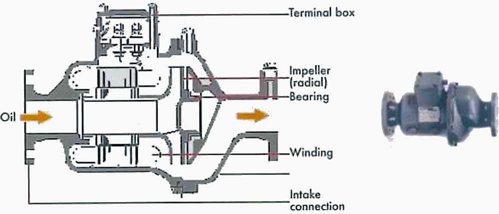
1.1 Axial Pumps with Radial Impellers
Axial pumps with radial impellers are used when there is high flow resistance in the fluid circuit, such as occurring when oil-to-air heat exchangers and oil-to-water heat exchangers are included. When the pump is switched off, only a very small quantity of oil can flow through the pump.
The thermo-siphonic effect is very small and hence little or no ON.. type cooling is available for the transformer.
Typically, an axial pump with a radial impeller might deliver a flow rate of between 25 m3/h and 300 m3/h at a nominal pressure head of 0.24 bar up to 2.2 bar.
Figure 1 – Typical views of an axial pump with radial impeller

1.2 Angle or Elbow Type Pumps with Radial Impellers
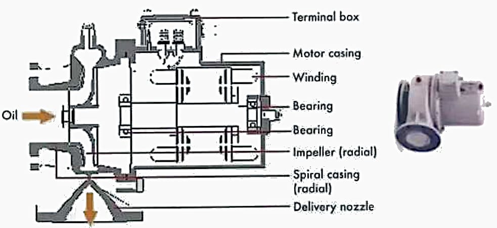
Angle or elbow pumps are a special form of oil circulation pump with radial impellers. They are also used for transformers with high flow resistance in the circuit such as when oil-to-air heat exchangers or oil-to-water heat exchangers are used.
They have the advantage of space saving.
Elbow-type pumps with radial impellers will typically deliver a flow rate of between 25 m3/h and 250 m3/h at a nominal pressure of 0.5 bar up to 1.3 bar.
Figure 2 – Typical vews of an Elbow Type Pumps with a Radial Impeller

1.3 Axial Pumps with Propeller-Type Impellers
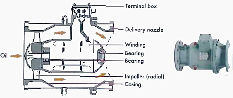
Axial pumps with propeller-type impellers are typically used for transformers that are equipped with radiators or radiator banks and have an ON.. cooling stage(s). When the pump is switched off, it offers very little restriction to thermo-siphonic flow and hence permits oil natural cooling where radiators are used.
An axial pump with propeller-type impeller will typically deliver a flow rate of 35 m3/h up to 300 m3/h at a nominal pressure of between 0.07 bar and 0.3 bar.
Figure 3 – Typical vews of an Axial Pumps with Propeller-Type Impellers

1.4 Determination of Required Pump Size
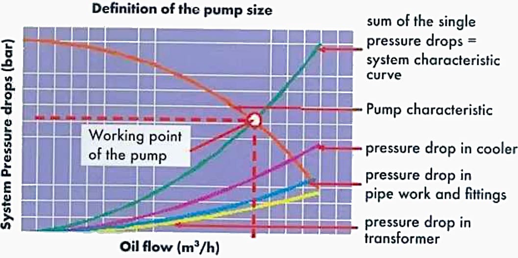
The size of pump is determined by the pressure drop in the complete cooling circuit against the desired oil volume flow rate of the cooling system, the number of pumps that will be operating in parallel, and the nominal bore of the pipe work to which the pump will be attached.
The cooling circuit comprises the transformer, its cooler, its pipe work, fittings and the pump.
The pump supplier will provide the appropriate pump characteristic curve. The intersection point between the pump characteristic curve and the system characteristic curve is the operating point of the pump. The properties of the pump oil volume flow, pressure and the noise level at the working point must fulfill all of the requirements of the cooling system of the transformer.
Figure 4 – Definition of the pump size

2. Transformer Fans
For air forced cooling of transformers or reactors with radiators (ONAF) or oil-to-air heat exchangers (OFAF or ODAF) axial flow fans are used in accordance with IEC and EN norms, unless otherwise specified. A three-phase or single-phase A.C. or D.C. motor can be used to drive the fan wheel. The fans can be equipped with an external or internal rotor motor.
The protection degree of the motor and the connection box is IPS4 as a minimum, for external rotor motors IP54 is normally the maximum achievable protection class.
Fans for radiator cooling have to be fitted with protective screens on both inlet and outlet sides.
Fans for oil-to-air heat exchangers are generally fitted with only one protective screen on the outside of the fan, because it is not possible for personnel to make contact with the fan blades on the heat exchanger tube side. The protection classes of the protective screens are IP2X in accordance with IEC and EN norms.
The fan assembly consists of motor, fan-casing, fan-wheel/blades and protection screen(s).
Figure 5 – Typical design of a transformer fan

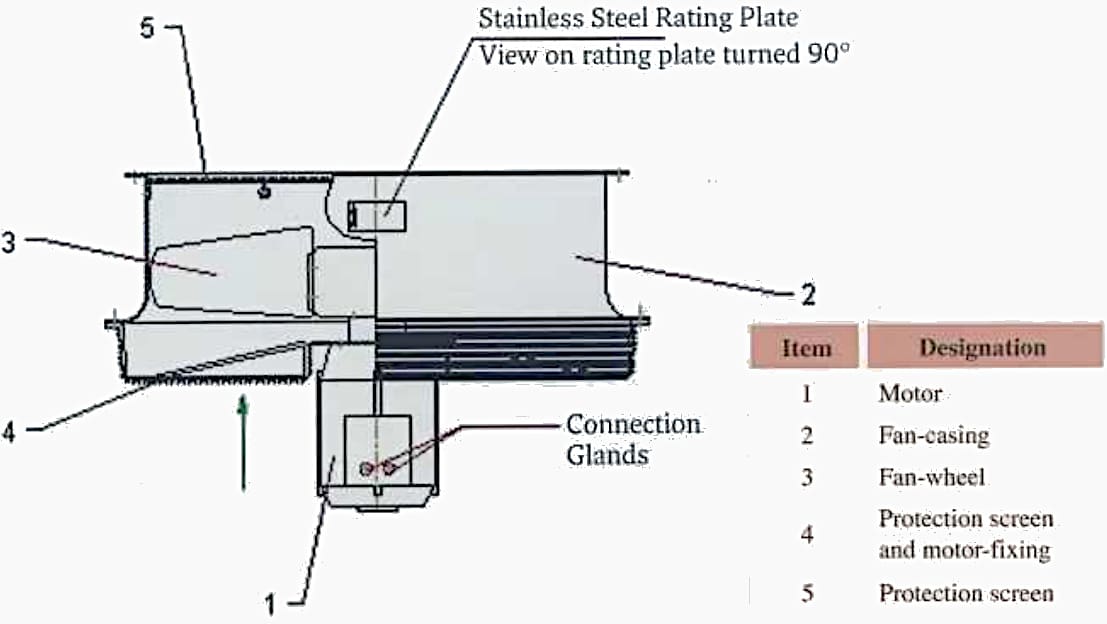
The relevant parameters for fans are the volume flow (m3/s), the static pressure (Pa), the noise level (dB) at the working point and the diameter of the fan wheel (mm). The typical characteristic of the axial fan is a high volume flow with a low static pressure. This corresponds to the requirements for the transformer cooling low pressure drop for small temperature differences.
The diameter of the fan wheel will ically range from 400 mm (for small power transformers wit radiators up to 1600 mm (for very large transformers with oil-to- air heat exchangers or radiator banks).
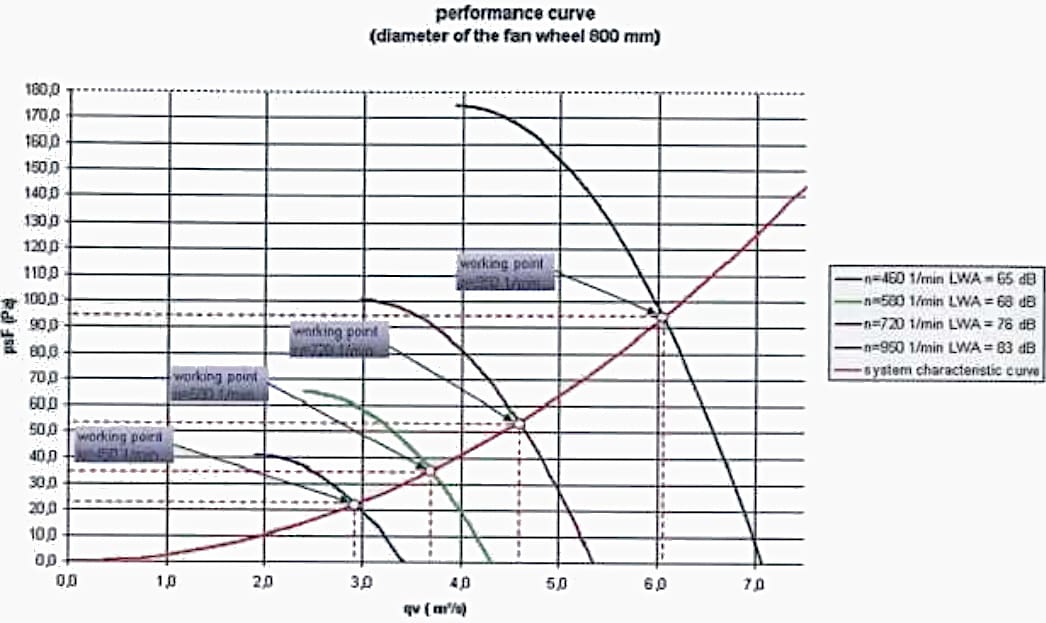
Figure 6 depicts the performance curves of a fan with an 800 mm wheel/blade diameter. This size of fan can be equipped with motors that are rated for different speeds. Each curve shown is a function of the speed of the fan and shows the volume flow, referring to a constant air density (here 1.2 kg/m’), depending upon the delivered static pressure of the fan.
The properties of the fan volume flow, static pressure and the noise level at the working point of the fan must fulfill the requirements of the cooling system of the transformer.
Figure 6 – Typical transformer fan performance curve

3. Cooling Radiators
Radiators are components of the cooling system. Cooling elements (panels) on the outside of the transformer tank provide an oil flow path to transfer heat from the transformer to ambient air.
Radiators are frequently the most competitive solution to cool a wide range of transformers.
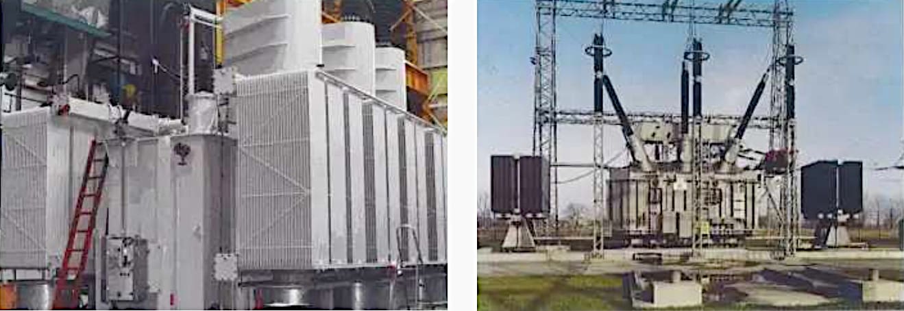
Radiators may be mounted directly on the transformer tank as shown in Figure 7 (right) or via an additional header (refer to Figure 8, left), or are arranged near the transformer as a separate cooler bank, as may be seen in Figure 8 (right).
Figure 7 – Left: Principles of cooling; Right: Tank mounted radiators

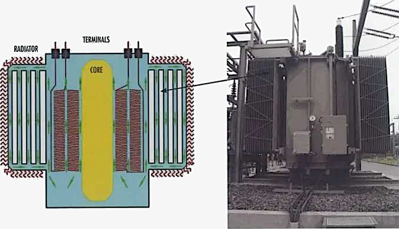
Figure 8 – Left: Transformer with additional header; Right: Transformer with separate radiator bank

Radiators are standardized by IEC and EN norms
- Radiator with flanges and elements having the same lengths
- Radiator with flanges and reduced height top connection
- Radiators with flanges and elements having different lengths
For radiators mounted directly on the tank special types can be used. Figure 9(b) is used to allow a tall radiator without the requirement of an additional header and without increasing the tank height.
Figure 9(c) can be used to meet the requirements of a railway loading gauge if the radiators are to remain fitted during transport.
For the largest transformer ratings, transformers housed in noise enclosures, or where site restrictions apply, the radiators can be located separately from the transformer on a cooler bank. The radiators are mounted on a framework that includes headers, and which is ground mounted.
Interconnecting pipe work and appropriate isolating valves are required for maintenance and erection purposes.
Figure 9 – Transformer radiator types

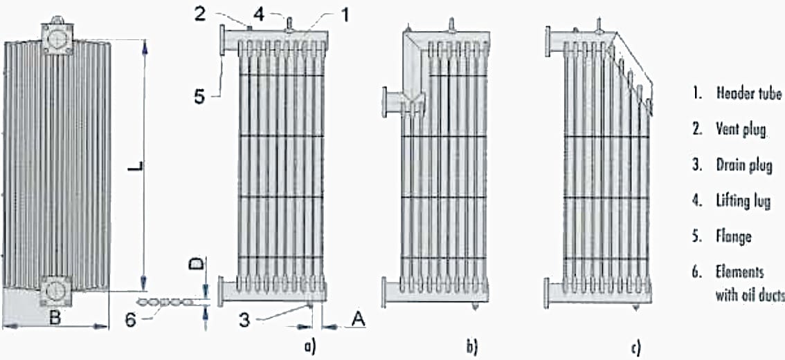
The radiator elements consist of two welded half shells made from steel sheets of 1.0 mm minimum thickness. Channels pressed into the surface of the radiators panels form the oil channels as shown in simplified sectional view in Figure 9. The thickness D of the element (6) is circa 12 mm, the pitch between element centers is normally 45 or 50 mm. This makes sure the dimensions of the oil and air channels are optimized for heat transmission.
The width of the panels B is in the order of 520 mm. The oil channel leads to the header tubes (1) via a special formed end at the top and bottom of the elements. The height of the radiator between the header tubes is selectable from 800 mm to 3 500 mm in steps of 100 mm.
A maximum number of 35 elements per radiator are possible.
Paintwork or galvanizing for corrosion protection has to be defined in accordance with the environmental conditions.
Further Study – Good practice in the design of concrete and steel structures in power substations
Good practice in the design of concrete and steel structures in power substations
4. Oil-to-Air Heat Exchangers
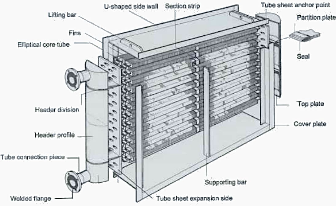
Oil-to-air heat exchangers (air blast coolers) are compact OFAF or ODAF coolers for the dissipation of heat to atmospheric air. These types of coolers are used to increase the cooling surface areas on both air and oil sides, whilst minimizing the overall cooler dimensions.
Moreover, a cooler that has a large footprint area also requires an extensive pit in which to capture oil in the event of a substantial oil leak. Figure 10 shows such a heat exchanger.
The principal components are elliptical ferrous tubes with fins, or circular copper tubes with aluminium or copper fins. They are fitted into steel plates, which in turn are attached to headers. Axial-flow motor driven fans are attached to the cooler body. Pumps will be used for oil circulation and will be connected to the header flange.
Figure 10 – Typical transformer oil-to-air heat exchanger

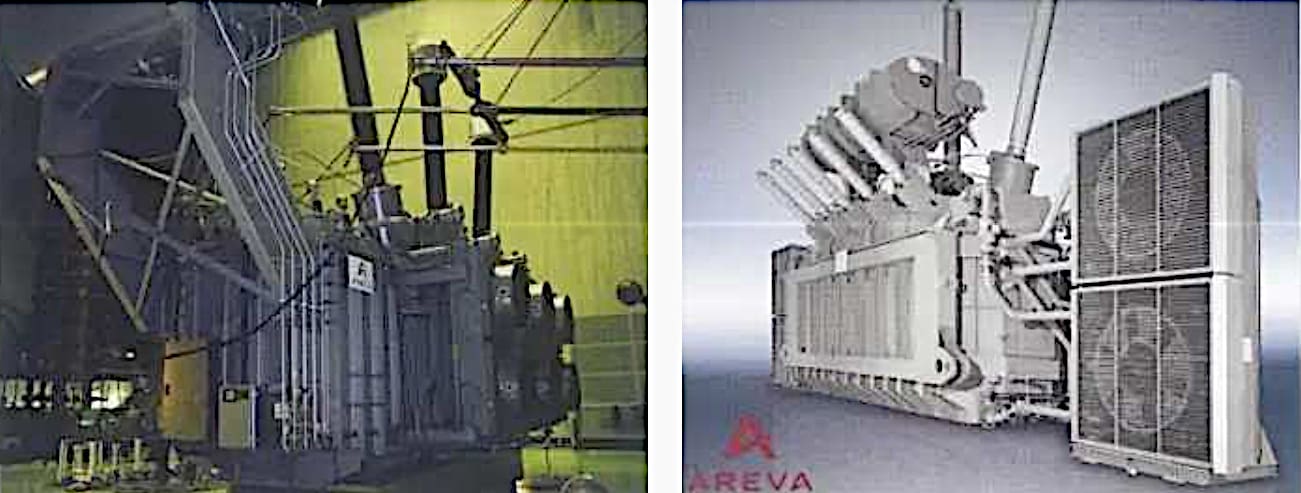
These coolers can be mounted either horizontally or vertically. They can be mounted directly on transformer tanks in a vertical position, for example as shown in Figure 11 (left), or can be arranged separately from the transformer as in Figure 11 (right). IEC and EN standards establish essential dimensions; the requirements to ensure interchangeability and adequate mounting of the oil-to-air heat exchangers.
One cooler can have one or more fans depending upon size and duty. Heat exchangers can be arranged in a variety of configurations to provide the required total cooling capacity e.g. one for 100% of rated cooling, or two units each giving 50% cooling, or four with 25% cooling etc.
A number of small cooler modules offer an additional advantage, that under light load conditions some of the coolers can have fans and pumps switched off, thereby saving energy.
Figure 11 – Transformer with Oil-to-Air Heat Exchanger installed vertically (left) and separately (right)

5. Oil-to-Water Heat Exchangers
OFWF or ODWF cooling of the transformer oil is provided by water instead of air and is a more efficient heat-transfer media, which means an even more compact heat exchanger than oil-to-air. The quality of the cooling water plays a crucial role in the selection of materials for the tubes, drains and water chamber.
The choice of materials of oil-to-water heat exchangers should be based on an analysis of the actual cooling water source, bearing in mind that the analysis could change if any of the processes also using the same water subsequently change.
Usually, in addition to the cooling modules (heat exchanger, pipe work, fittings and the pump) required for 100% rating, one complete cooling module is added as a standby.
Within the coolers, cooling water flows through the insides of the tubes and oil flows on the outside. The tube bundle is fitted with baffles to provide cross flow of the oil for improved cooling efficiency, and is housed within a closed cylindrical shell. Water plenum chambers are provided at both ends of the tube bundle. These chambers may be designed as single pass (i.e. water inlet and outlet at opposite ends of the heat exchanger) or double pass (i.e. water inlet and outlet at the same end).
Water connections are made to flanges, one for cold-water inlet and one for hot-water outlet. The oil side connections are also flanged one for hot-oil inlet and the other for cold-oil outlet. These are connected to the transformer via suitable pipe work, valves and flexible couplings.
Pumps are definitely required to produce the designed oil flow rate, and frequently water pumps may be required also depending upon the available head of water at the connections to the heat exchanger.
Oil-to-water heat exchangers are basically of two different design categories: single and double tube coolers in accordance with IEC and EN standards.
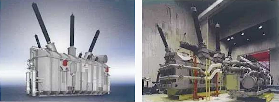
Figure 12 – Left: 350 MVA ODWF transformer with oil-to-water heat exchangers on the tank – supplied as 4 cooling modules plus one standby; Right: 1100 MVA ODWF transformer with oil-to-water heat exchangers separated from the tank – also 4 cooling modules plus one standby

5.1 Single Tube Oil-to-Water Heat Exchangers
This type of water cooler is the lowest cost solution, but may not be cost-effective. It is very important that under all operating conditions, (the worst is usually when the oil-circulating pump is stopped and the oil temperature is at its lowest), the oil pressure outside the heat exchanger tubes is always of a higher value than the water pressure.
The reason for this proviso is that in the event of a leak in the heat exchanger water cannot leak into the oil. The transformer is therefore protected against water ingress which would have disastrous consequences.
There is, however. a risk that the cooling water could be contaminated with oil. In this instance, precautionary measures must be taken to avoid environmental damage by providing suitable drainage control.
In view of the problems of potential leakages in either direction, this type of cooler is unlikely to be specified except for the repair of existing equipment.
Good Reading – Transformer Stories: From Testing and Analysis to Maintenance Case Studies
Transformer Stories: From Testing and Analysis to Maintenance Case Studies
5.2 Double Tube Oil-to-Water Heat Exchangers
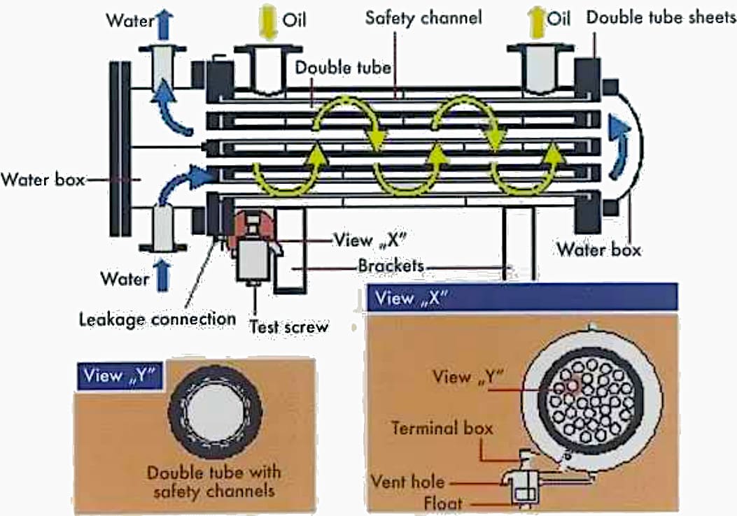
Unlike the single tube oil-to-water heat exchanger, the bundle of tubes in this type of cooler are equipped with double tube sheets and double tubes with safety channels between them as shown in Figure 13. In this case, in the event of a leak, water or oil depending upon which side the leakage develops, flows into the safety channels of the tubes and between the double tube sheets.
To detect a leakage early, the channel drain of the heat exchanger is fitted with a leakage monitor. A micro-switch activated by a float is fixed within a transparent reservoir for collecting the leaked oil or water that has been collected in the safety channels.
The switch initiates an alarm when only a few cc have been collected in the reservoir.
This is, without a doubt, a cost-effective solution. As an added bonus, not only does the double tube oil-to-water heat exchanger provide safety for the transformer and for the environment but it also means that the water pressure can be higher than the oil pressure.
Figure 13 – Sectional view of double-tube oil-to-water heat exchanger

6. Attachment (PDF): Transformer Engineering Handbook
Download: Transformer Engineering Handbook (for premium members only):
Reference: Areva

Hi, I’m electrical engineer working in power system ,
please I need help,
How I can calculate the numbers of cooling fans for power transformer ?
best wishes.