
Power System Safety Rules
To be honest, working at switchyards and substations requires a thorough and true understanding of hazards and control measures before progressing to Power System Access. Only individuals with the proper authorization should operate within switchyards or high voltage zones.

 Thumb Rules for Working in Switchyard and HV Areas
Engineers working in substations frequently presume that any earthed object can be securely contacted. A low ground resistance in a substation does not inherently ensure safety. The relationship between the overall resistance of the earth system and the max. shock current a person may encounter is not straightforward.
Consequently, a substation with comparatively low ground resistance may pose a hazard, but another substation showing significantly high resistance may be deemed safe or isolated safe via meticulous design.
For example, when a substation is fed by an overhead line lacking a shield or neutral wire, a low grid resistance is crucial. The majority or entirety of the total ground fault current enters the earth, resulting in a frequently abrupt increase in the local ground potential.
When a shield wire, neutral wire, gas-insulated bus, or buried cable feeder is installed, a portion of the fault current returns through this metallic conduit directly to the source. The metallic link offers a low impedance parallel route to the return circuit, resulting in a comparatively minor increase in local ground potential.
In this technical article, the terms ‘must‘ and ‘must not‘ denote obligatory requirements that must be followed to. The terms ‘should‘ or ‘should not‘ are employed when distinguishing safe and low-risk work practices.
The article contains extracted pictures from Transgrid’s Power System Safety Rules.
Remember, we all have a responsibility to work safely and look out for each other in a substation.
- Personal Protective Equipment (PPE) Saves Life
- Security of a Substation HV Areas
- Avoiding Hazard Situations:
- Attachment (PDF) 🔗 Download ‘Electrical Safety Handbook For Engineers’
1. Personal Protective Equipment (PPE) Saves Life
Without proper Personal Protective Equipment (PPE), don’t even think about entering any substation. You need to wear the following PPE to work in any power substation:
- Long sleeve shirt
- Long trousers
- High visibility shirt or vest
- Safety footwear
- Safety eyewear
- Protective gloves (on clip)
Figure 1 – Proper Personal Protective Equipment (PPE)

1.1 What else do you need? Safety Helmet of Course.
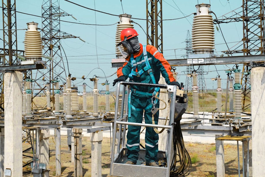
Accessing High Voltage (HV) zones necessitates the use of a safety helmet. Don’t even think about entering substation areas without it.
Figure 2 – Substation engineers wearing safety helmets

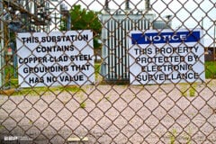
2. Security of a Substation HV Areas
Substations and high-voltage areas must be secured to prevent unauthorized access to the facility.
When entering a substation:
- Do not allow unauthorised persons to enter the substation.
- Doors and gates:
- Must only be unlocked or open when in immediate use;
- Must be closed and locked immediately after using; and
- Any found open or unlocked, must be closed and locked.
When leaving a substation:
- All doors and gates must be closed and locked; and
- Security alarms reset by the last person to depart.
3. Avoiding Hazard Situations
A prestart hazard assessment must be conducted prior to commencing any work. Alongside the hazards specified in Work in Buildings and Carparks, the subsequent hazards must be acknowledged, and suitable safety measures enforced.
3.1 Near Approach to Energised High Voltage Conductors
Proximity to or contact with exposed High Voltage (HV) conductors can result in serious injuries or fatalities.
Figure 3 – Near Approach to Energised High Voltage Conductors

3.1.1 Workers and Safe Distance Approach
Switchyards and high voltage areas are often designed to ensure that an average individual may safely raise their hand beneath energized high voltage lines.
Figure 4 – Persons and Safe Distance Approach

Safe Approach Distances for workers and other persons must be maintained per the Safe Approach Distances to Exposed Conductors table.
Table 1 – Safe Approach Distances for Persons
| Nominal Voltage (kV): | 11-33 | 66 | 132 | 220 | 275 | 330 | 500 |
| Distance (m) | 0.7 | 1.0 | 1.2 | 1.8 | 2.3 | 3.0 | 3.9 |
When operating near high voltage conductors, the primary guideline for maintaining Safe Approach Distances is to remain at ground level and ensure that tools and equipment are kept below shoulder height.
Ladders, conduit or pipe lengths, and other elongated objects represent a risk if not managed properly to prevent proximity to exposed high-voltage conductors.
Figure 5 – Good and wrong way managing ladders

Utilize non-conductive measuring tapes or laser measuring instruments. A second individual should provide assistance to prevent wind from displacing tapes in proximity to high-voltage conductors. Refer to Figure 6 (left).
Metal measuring tapes and metal-reinforced measuring tapes are prohibited in switchyards and high-voltage areas. Refer to Figure 6 (right).
Figure 6 – Good and wrong way of using measuring tape

Fire extinguishers labeled ‘Suitable for Usage on Electrical Fires’ are designated for Low Voltage circuits exclusively and must not be utilized on or near High Voltage equipment. Refer to Figure 7 (left).
Flame serves as an effective conductive medium, necessitating caution while operating flame-producing equipment in proximity to energized high voltage exposed conductors.
Refer to Figure 7 (right).
Figure 7 – Wrong ways of using Fire extinguishers

High voltage conductors covered with colored tape, rubber or other fabric, must still be treated as exposed HV conductors.
Figure 8 – Be careful with high voltage conductors covered with colored tape or rubber

3.1.2 Switchyard No Go Areas and What if You Go
Certain high voltage equipment is enclosed within a “High Voltage Cage,” a completely gated or walled space secured with a specialized lock, housing high voltage exposed conductors that do not adhere to typical safety clearances. Access to these regions is permitted only after isolation and the issuance of an Access Authority.
If a High Voltage Cage gate is discovered to be unlocked, refrain from entering and report it immediately.
Figure 9 – High voltage cage pose a huge danger

3.2 Vehicles Working in Substation Areas
Large trucks, as well as those equipped with extended antennae or elevated cargo, may encroach upon minimum safe approach distances while traversing a switchyard or high-voltage area. Designated switchyard and high-voltage area roadways are typically engineered to allow vehicles under 2.4 meters in height to traverse safely beneath energized high-voltage cables.
Radio antennas must be detached or retracted.
Figure 10 – Approach of vehicle without and with antenna

Vehicles and movable equipment secured for transportation may operate in switchyards and high-voltage areas, provided that Safe Approach Distances for Vehicles are upheld.
A Mobile Plant Assessment professional must be consulted to ascertain safe routes for vehicles operating off designated roadways and for all vehicles above 2.4m in height, including the load.
Figure 11 – Correct and wrong approach of a high vehicle

Where there is a possibility of coming within Vehicles – Safe Approach Distances to Exposed Conductors a person authorised Mobile Plant Assessment must be consulted before any work commences.
Table 2 – Safe Approach Distances for Vehicles (including mobile plant stowed for transit)
| Nominal Voltage (kV): | 11-33 | 66 | 132 | 220 | 275 | 330 | 500 |
| Distance (m) | 0.7 | 1.0 | 1.2 | 1.8 | 2.3 | 3.0 | 3.9 |
3.3 Mobile Plant (Cranes, Excavators, Elevated Work Platforms)
Mobile plant, such cranes, excavators, or elevated work platforms, may encroach upon minimum safe approach distances when functioning near energized high voltage exposed conductors.
Figure 12 – Safe and unsafe approach distance for mobile plant, such cranes, excavators, or elevated work platforms

Safe Approach Distances for mobile plant (considered at full extension) must be maintained per Mobile Plant – Safe Approach Distances to Exposed Conductors.
Figure 13 – Safe Approach Distances for mobile plant

Before commencing any work in proximity to Mobile Plant – Safe Approach Distances to Exposed Conductors, consultation with an authorized Mobile Plant Assessor is mandatory.
Table 3 – Safe Approach Distances for Mobile Plant
| Nominal Voltage (kV): | 11-33 | 66 | 132 | 220 | 275 | 330 | 500 |
| Distance (m) | 3.0 | 3.0 | 3.0 | 6.0 | 6.0 | 6.0 | 8.0 |
3.4 Induced Voltages and Currents (Induction)
Alternating current (AC) traversing high voltage cables in power substations generates electric and magnetic forces. The intensity of these fields can induce voltages and currents in surrounding objects that are not grounded.
3.4.1 Danger to Substation Workers
A worker shielded from the substation by the rubber bottoms of their boots accumulates charge in the electric field, and upon contact with substation structures, the resultant discharge may be perceived as a minor shock.
Certain medical implants, including pacemakers, may be influenced by electric and magnetic fields. Should you possess such a device, it is imperative to consult with your doctor and obtain authorization before to accessing switchyards or high-voltage locations.
Figure 14 – Warning about medical implants due to electric and magnetic fields in a substation

3.4.2 Earthing of Objects
Rules regarding the earthing of objects:
- Extended metallic structures, such as temporary fences, must be grounded at regular intervals.
- Substantial vehicles and mobile equipment stationed in areas of elevated induction must be interconnected to the substation grounding system.
3.4.3 Refuelling of Equipment and Plant
Refueling of equipment and machinery has to take place in a location distant from energized high-voltage cables. For stationary equipment that cannot be moved, a static bonding kit or an other control device must be employed to prevent sparks during refueling.
Figure 15 – Correct and wrong way of refueling of substation equipment and machinery

3.4.4 Working on Isolated HV Equipment
While operating on isolated high voltage equipment, induced voltages and currents may arise from proximate live high voltage wires, high voltage switching, or electrical malfunctions in neighboring apparatus.
Further Study – The problem of induced voltages in control cables in high voltage substations
The problem of induced voltages in control cables in high voltage substations
3.4.4.1 Bonding Leads
A bonding lead, when utilized alongside Access Authority and mobile plant earthing, establishes a low impedance connection between two objects—potentially at differing voltages—to assure the maintenance of equipotential conditions during operations.
They may also be employed to dissipate capacitive voltages from disconnected equipment, which can remain susceptible to capacitive coupling and resultant induced voltages.
Figure 16 – A bonding lead provides a low impedance connection between two objects

3.4.4.2 Bonding Lead Requirements
A bonding lead must have a minimum cross-sectional area of 35mm² copper and is affixed to equipment such as EWPs by a permanent connection, an earthing stub, or a screw-action earthing clamp. The bonding lead must be affixed to the conductors utilizing an MT815S clamp. To avoid confusion with fault-rated earthing equipment, a bonding lead must not be yellow.
When it is unfeasible to attach the bonding lead and MT815S clamp to equipment like the T or V junction in a circuit breaker head or the central moving contact of a disconnector, an appropriate clamp connection must be employed. The appropriate clamp will be contingent upon the attachment position.
Exercise caution while utilizing bonding leads, as the MT815 clamp will not detach if it remains connected to the conductors or equipment.
3.4.4.3 Applying and Removing a Bonding Lead
When attaching a bonding lead, ensure that you avoid putting it into the electrical circuit. Where applying or withdrawing the bonding lead to the conductors, ensure that the hand applying the lead and any other body parts remain behind the end of the bonding lead and away from the conductors to be bonded (utilize an MT815S application handle where feasible).
Figure 17 – Correct and wrong way of applying or removing the bonding lead to the conductors

By contacting the conductor with their hand, the worker has integrated their body into the discharge circuit. Refer to Figure 18 (left).
Improper bonding positions the hand near the conductors, increasing the potential of accidental contact. Refer to Figure 18 (on the right).
Figure 18 – Left: By touching the conductor with their hand, the worker has made their body part of the discharge circuit. Right: Incorrect bonding lead places the hand in close proximity to the conductors and introduces a risk of inadvertent contact.

3.5 Enclosed Spaces (GIS Building)
Certain Gas-Insulated Switchgear (GIS) facilities, basements, and tunnels may possess site-specific protocols concerning the discharge of gas and/or the operation of moving components on high-voltage equipment.
Site-specific risk assessments and signs must be evaluated prior to initiating work on-site.
Figure 19 – Gas-Insulated Switchgear (GIS) facility

3.6 Earthing Systems
Every substation is (or MUST be) equipped with an earthing system that is interconnected and designed to guarantee that equipotential conditions are present.
Figure 20 – Substation earthing grid

3.6.1 Damage and Dangerous Voltages
There is a possibility of harmful voltages occurring if the earthing system is damaged.
Figure 21 – If the earthing system is damaged dangerous voltages may occur

Any damage to grounding systems must be notified without delay (see to Figure 22 on the left). Avoid from approaching, touching, or attempting repairs (see to Figure 22 on the right).
Figure 22 – Left: Any damage to earthing systems must be reported immediately. Right: Do not approach, touch or attempt repairs.

3.6.2 HV Equipment Earth Connections
Work involving the connection, cutting, disconnection, or potential damage to earthing connections of high voltage equipment must only be conducted after the HV equipment has been isolated and proven safe for operation.
Warning labels denote single point earth connections that are exposed to extremely hazardous voltages and currents during standard working settings. Refer to Figure 23 on the left.
Dangerous voltages may occur if earth connections between HV apparatus and the earthing system are removed whilst the apparatus is in service. Refer to Figure 23 right.
Figure 23 – Warning labels identify single point earth connections which are subject to highly dangerous voltages and currents under normal operating conditions.

3.6.3 Switchyard Earth Grid Voltage Rise & Transferred Earth Potentials
Substations may experience hazardous voltage surges owing to problems in the power system. Any external connection to a switchyard facilitates the transfer of hazardous earth potentials (voltage) to or from a substation’s grounding grid.
Figure 24 – Any external connection to a switchyard facilitates the transfer of hazardous earth potentials

While operating outside the substation perimeter, you must refrain from connecting any of your equipment or mobile machinery to the fence or to any apparatus within the substation.
Figure 25 – Operating outside the substation perimeter (the wrong way)

Before establishing any new connection, such as a transmission line to a substation, an Electrical Engineer’s evaluation will identify the requisite safety measures to be enforced by the project team on-site.
Figure 26 – Connecting new transmission line to a substation

3.6.4 Excavation or Digging in a Switchyard
Excavation or digging in a switchyard or high-voltage area poses a risk of encountering buried utilities, including electrical lines and grounding systems. Prior to the commencement of any excavation:
An authorized Excavation Permit must be obtained.
In instances where there is a risk of compromising the substation earthing system, the permit will include certain conditions, including the installation of bridging leads by an individual authorized to manage Bridging Earthing Grids.
Figure 27 – An approved Excavation Permit must be issued

While conducting excavation activities:
- Mobile equipment must be connected to the substation grounding system via a trailing earth lead;
- Bridging leads may only be added or removed by an authorized individual.
- Bridging Earthing Grids;
- Only non-destructive excavation methods shall be employed within 200mm of identified services; and
- A spotter is required to detect any unforeseen services in the excavation zone.
Figure 28 – Rules during excavation work

3.7 Work in the Vicinity of HV Cables and Sealing Ends
During operation, hazardous voltages may arise if the connections between the high-voltage cable and the grounding system are severed or compromised.
Work involving the connection, cutting, disconnection, or potential damage to earthing connections of HV cables must only be conducted after the HV cable has been isolated and isolated safe for operation.
See Figure 29.
Figure 29 – Hazardous voltages may occur if the connections between the HV Cable and the earthing system are removed or damaged

4. Attachment (PDF): Electrical Safety Handbook For Engineers
Download: Electrical Safety Handbook For Engineers (for premium members only):
Source: Power System Safety Rules by Transgrid
Related electrical guides & articles


Edvard Csanyi
Hi, I'm an electrical engineer, programmer and founder of EEP - Electrical Engineering Portal. I worked twelve years at Schneider Electric in the position of technical support for low- and medium-voltage projects and the design of busbar trunking systems.I'm highly specialized in the design of LV/MV switchgear and low-voltage, high-power busbar trunking (<6300A) in substations, commercial buildings and industry facilities. I'm also a professional in AutoCAD programming.
Profile: Edvard Csanyi

I one followers of @edvard csanyi, I am certified NETA level 3 and working most on commissioning works from LV to EHV from commercial like airports and nuclear power plant and refinenaries and now currently working as consultant in commissning authority in neom oxagon and still I am visiting this portal to get some new innovations in engineering aspects as we grow and more exposed to electrical engineering field specially in nature of projects be measure the safety regulations local and international applicable standards. I am grateful to have a public post from this portal for references and guidance as I believe electrical can’t be easily understood by only reading it unless you are exposed and expereince directly specially with trained and continuous works in standards projects. I am more than 15 years in industry working different nature of projects stiull unable to cope up deep electrical power systems approached and keep moving specially I am now working on my thesis in professional electrical engineer upgrades. Thank you Engr. Edvard.
Good day
I’m interested in joining this group and share more details of this particular industry,I’m a retired senior technician but I worked in different sectors as technician,I can say from steel industry to electricity generation and projects
Regards
Sello Nicholus Mashego
[email protected]
0732603855