
Three-Phase Basics & Hot Wires
We all know that an electric current needs a circuit (a complete circle) before it can flow. A single-phase wye circuit can be a phase and a neutral with the current flowing through the “hot” wire and returning to the source through the neutral. Most utility circuits consist of three phases.
 Three-phase basics and terms that students often mix
It’s important to note that a three-phase circuit is not three different single-phase circuits, but one circuit with all three phases interconnected. Each phase helps to complete the circuit by acting as the return path for the other two phases.
A live conductor in a circuit tends to be called a phase because when three-phase voltages and currents are generated, each of the three conductors gets its voltage and current at a certain phase of a cycle.
Ok, let’s get started with the characteristics of three-phase circuits, then continue with delta- and wye-connected electrical systems and conclude the article with three-phase power, calculations and examples.
- Characteristics of Three-Phase Circuits
- Delta-Connected Systems
- Wye-Connected Systems
- Three-Phase Power
1. Characteristics of Three-Phase Circuits
1.1 Why Three Phase?
The effect of three-phase power as compared to single-phase power is similar to the effect of a six-cylinder engine as compared to a single-cylinder engine. A six-cylinder engine produces a smoother six small pulses per cycle while the single-cylinder engine produces one large pulse per cycle.
The values of the voltage and current in each of the three phases overlap with the other phases; therefore, three interconnected phases provide a smoother power than the relatively more pulsating power of a single phase. Three-phase current supplies a rotating magnetic field. Even though the power on each individual AC phase pulsates when it goes through the AC cycle, the sum of the power in all three phases at any point is constant.
With the same voltage and current per phase, a three-phase system needs only one additional wire (without a neutral, there is a 50% increase in conducting material) over a single-phase system but increases the circuit capacity by 73%.
A three-phase circuit can carry twice as much load as a single-phase circuit while maintaining the same voltage.
Suggested Course – AC Circuit Analysis: Fundamentals Course for Electrical Engineers
AC Circuit Analysis: Fundamentals Course for Electrical Engineers
Go back to the Contents Table ↑
1.2 Generation of Three-Phase Power
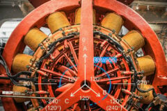
A simplified three-phase generator, as illustrated in Figure 1, shows three coils mounted on the armature at 120 degrees apart. Each coil generates an AC and voltage, but the power generated in each coil reaches its peak and direction at 120 degrees apart.
Commercial generators mount many coils on the stator and many magnets on the armature. The individual coils are wired so that they are connected together as three circuits 120 degrees apart. Each of the three circuits becomes a phase of a three-phase circuit.
Figure 1 – Simplified three-phase generator

Go back to the Contents Table ↑
1.3 Phases 120 Degrees Apart
When three phases are 120 degrees apart, as shown in Figure 1, the values also can be shown in graph form as in Figure 2. The first vertical line in Figure 2 shows the values being generated in Figure 1.
Phase A, at 90 degrees, is generating at the maximum value, phase B, at 210 degrees is climbing towards the zero value, and phase C, at 330 degrees, is approaching the maximum return or negative value.
The second vertical line shows what is happening to the power generated in each phase when phase A is 120 degrees (one-third of the way) into the cycle, phase B would be 240 degrees (two-thirds of the way) into the cycle, and phase C would be at 360 degrees (at the end, which is also the beginning) of the cycle.
Even though each phase has the same voltage, they are out of phase with each other and there is a voltage difference between them.
Figure 2 – Relationship of three phases
When the load on each phase is identical, the instantaneous power output of the three phases added together is constant. When one phase of a three-phase circuit reaches a peak voltage, another phase is close to zero volts and the third phase is on the return flow. As simple as it is!
So, each phase is 120 degrees out of phase with the other phase. The voltage and current in each phase are 1/180 second, or one-third distance in a cycle behind another phase.
Related electrical guides & articles


Edvard Csanyi
Hi, I'm an electrical engineer, programmer and founder of EEP - Electrical Engineering Portal. I worked twelve years at Schneider Electric in the position of technical support for low- and medium-voltage projects and the design of busbar trunking systems.I'm highly specialized in the design of LV/MV switchgear and low-voltage, high-power busbar trunking (<6300A) in substations, commercial buildings and industry facilities. I'm also a professional in AutoCAD programming.
Profile: Edvard Csanyi
