Terminals, isolating links & bars
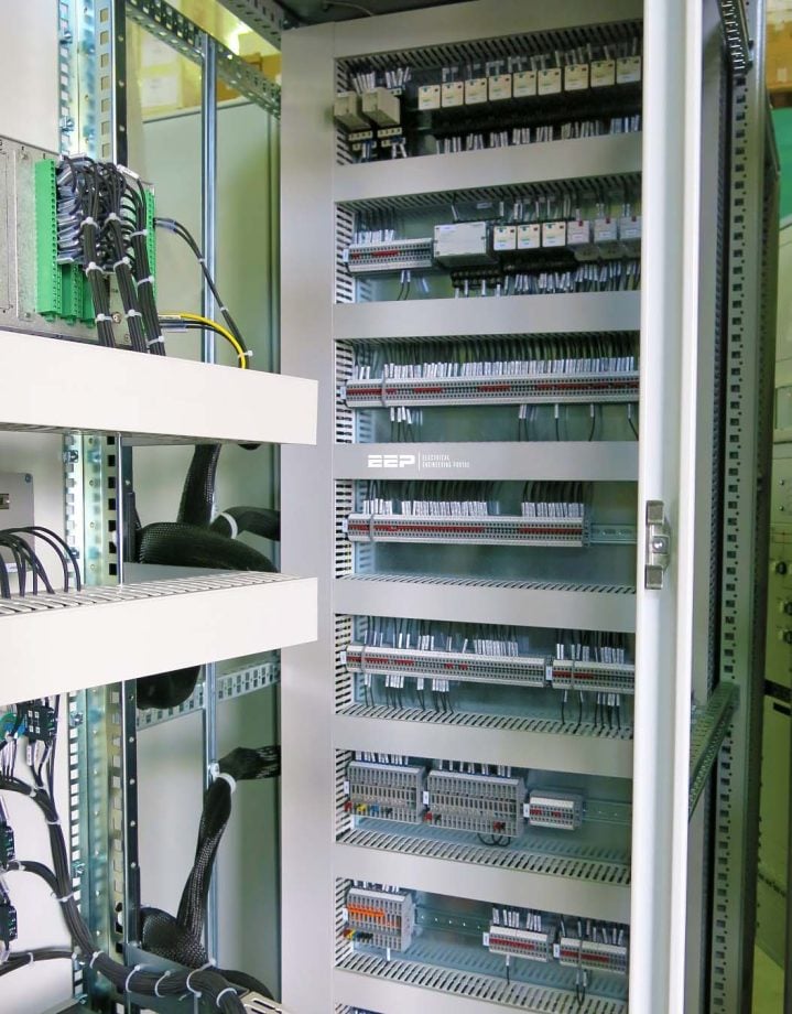
Terminals and other connecting elements, such as CT/VT shorting and isolating links, test blocks, and earthlings, often need to be better understood in analysing wiring diagrams and schematics. This can badly impact the testing and maintenance process, and sometimes, it can cause fatal injuries to personnel.

This technical article aims to take you on a journey through the fundamental terminals and other connecting elements of wiring diagrams and electrical schematics and to delve into the minute intricacies of the components that form them.
From the familiar male and female terminals that form the bedrock of electrical connections to the current and transformer shorting and isolating systems that safeguard the integrity of our circuits, we explore the key concepts, symbols, and functionalities that define the landscape of electrical engineering.
As we unravel the mysteries of male and female terminals, decipher the symbols for plugs and terminals, and explore the intricacies of transformers, protection systems, and beyond, our goal remains clear:
To empower you with the tools and understanding necessary to harness the power of electrical schematics and components in your own engineering endeavors.
- Male Terminal in Schematics
- Female Terminal in Schematics
- Symbol for Plug and Terminal
- Male Terminal Control Circuit
- Female Terminal in Control Circuit
- Connection Bar” or “Jumper”:
- Open Connection Bar (No Jumper Installed):
- Multi-terminal and Multiplug Connector:
- Current Transformer Shorting and Isolating Links:
- Voltage Transformer Isolation Links:
- Test Block in Protection and Control Panels
- Connection to Chasis
- PE Connection Point
- Earth/Ground Connection
- Main Conductor Symbol
- Secondary Conductor
- BONUS (PDF) 🔗 Download Operating and Maintaining Power Plant Equipment Guide
1. Male Terminal in Schematics
In schematic diagrams, a “male terminal” refers to a connector or contact point typically characterized by a protruding pin or prong that inserts into a corresponding “female terminal”. Male terminals are often found on components such as switches, relays, connectors, or integrated circuit packages.
They are designed to establish electrical connections with other components, devices, or circuitry, facilitating the transmission of signals, power, or data within an electrical system. The term “male” is used to describe these terminals because of their projecting nature, which allows them to be inserted into receptacles or sockets with corresponding female terminals.
Figure 1 – Symbol for the male terminal in schematics


2. Female Terminal in Schematics
In schematic diagrams, a “female terminal” refers to a connector or contact point that typically features a receptacle or socket into which a corresponding “male terminal” can be inserted. Female terminals are commonly found in components such as connectors, jacks, plugs, or sockets.
They are designed to accept the insertion of male terminals, establishing electrical connections between components, devices, or circuitry. The term “female” is used to describe these terminals because of their receptacle nature, which allows them to receive and make contact with the projecting pins or prongs of male terminals.
Figure 2 – Symbol for female terminal in schematics


3. Symbol for Plug and Terminal
In schematic diagrams, “plug” and “terminal” are two components commonly used to establish electrical connections within circuits:
Plug
A plug is a connector designed to be inserted into a corresponding receptacle, typically featuring male terminals. Plugs are often used to connect portable devices or components to a power source or to other devices within a circuit. They can vary in design depending on their intended application, such as audio jacks, power connectors, or data connectors.
Terminal
A terminal refers to a point in a circuit where electrical connections are made or terminated. Terminals can be male or female and are often represented in schematic diagrams as small nodes or connection points. They serve as the interface for connecting wires, components, or other conductors within a circuit.
Terminals can be found on various components such as switches, relays, connectors, or integrated circuit packages.
Figure 3 – Symbol for plug and terminal in schematics


4. Male Terminal Control Circuit
In the context of a control circuit, a “male terminal” typically refers to a connector or contact point within the control circuit that features a protruding pin or prong designed to be inserted into a corresponding “female terminal.” These male terminals are often found on components such as switches, relays, connectors, or integrated circuit packages within the control circuit.
They play a crucial role in facilitating the flow of control signals within the circuit, allowing for the operation and coordination of different elements within the control system.
5. Female Terminal in Control Circuit
In the context of a control circuit, a “female terminal” refers to a connector or contact point characterized by a receptacle or socket designed to receive and make contact with a corresponding “male terminal”.
Female terminals within a control circuit serve as points of connection for receiving male terminals from other components or devices. They enable the establishment of electrical connections necessary for the transmission of signals or control commands within the circuit.
Female terminals play a crucial role in facilitating the interaction and coordination between different components or subsystems within the control system, allowing for the effective control and operation of various devices or processes.
Figure 4 – Female and male terminals of control circuit


6. Connection Bar” or “Jumper”
In electrical circuits, a “closed connection bar” or “jumper” refers to a conductive element that bridges or connects two or more points within a circuit, creating an uninterrupted electrical pathway.
Essentially, it serves to close a circuit, allowing current to flow between the connected points.
Closed connection bars are commonly used in circuit design for several purposes:
Membership Upgrade Required
This content is not available in your premium membership plan. Please upgrade your plan in order to access this content. You can choose an annually based Basic, Pro, or Enterprise membership plan. Subscribe and enjoy studying specialized technical articles, online video courses, electrical engineering guides, and papers.
With EEP’s premium membership, you get additional essence that enhances your knowledge and experience in low- medium- and high-voltage engineering fields.
Limited Time Gift! – Save 10% on Pro Membership Plan with code 110VDC
Copyright Notice
This technical article is protected by U.S. and international copyright laws. Reproduction and distribution of PDF version of this technical article to websites such as Linkedin, Scribd, Facebook and others without written permission of the sponsor is illegal and strictly prohibited.© EEP-Electrical Engineering Portal.
Related electrical guides & articles
Premium Membership
Muhammad Kashif
Muhammad Kashif Shamshad is an Electrical Engineer and has more than 17 years of experience in operation & maintenance, erection, testing project management, consultancy, supervision, and commissioning of Power Plant, GIS, and AIS high voltage substations ranging up to 500 kV HVAC & ±660kV HVDC more than ten years experience is with Siemens Saudi Arabia.Profile: Muhammad Kashif


