Safety and Switching Rules
This technical article describes the safety rules the switching operator must comply with when undertaking switching, and providing access for others required to work on the electrical network. We’ll describe the critical matters relating to safe switching operations, it is applicable to both distribution and transmission switching.

 Substation Safety and Switching Rules You MUST Follow
Also detailed are the principles and practice of isolation and earthing, permits and barriers, locking and tagging. Details are provided on common switching operation tasks, the practical checks before and after switching apparatus and switching related hazards.
Switching operators are authorised by Power Utility and usually responsible for:
- Field switching of non-SCADA controlled apparatus associated with.
- Interconnection, creation of isolation points, program earthing and the reverse sequence switching for restoration.
- Disabling remote or automatic operation of apparatus.
- The issuing and cancellation of work permits.
- The flagging and barricading of safe working areas inside switchyards, and
- Installing appropriate signs.
So, whether you are sitting at the desk in the Control centre, design office, or working directly in the substation field, it’s imperative to be familiar with the safety and switching rules in substation areas under voltage.
- Tagging, Locks and Barriers:
- Common Switching Operations:
- Switchgear Pre- and Post-switching Checks:
- Switching-related Hazards:
- Attachment (PDF) 🔗 Download ‘How to Properly Test a Protection System & Prevent False Tripping and Unnecessary Outages’
1. Tagging, Locks and Barriers
Control and warning tags, locks and barriers are methods used to warn against and prevent the operation of electrical switching devices. Note that the formal term used by most Utilities worldwide is tag, however the term label is interchangeable and often used.
The following tags are used by switching operators:
- Danger–Do Not Operate
- Caution–Vicinity Work in Progress
- Danger–Restricted Use
- Warning–Out of Service.
1.1 Danger–Do Not Operate Tag
The Danger–Do Not Operate tag is an approved tag attached to electrical apparatus as an instruction against the operation of that electrical apparatus. It is used to protect all parties from inadvertent operation of the apparatus at the isolation points.
Danger–Do Not Operate tags MUST only be used in conjunction with switching programs and electrical apparatus access requirements.
Each Danger–Do Not Operate tag must be securely attached in a prominent position to the electrical apparatus being used as a point of isolation. The electrical apparatus to be worked on must not have a Danger–Do Not Operate tag attached.
Figure 1 – Danger–Do Not Operate tag

1.2 Caution! Vicinity Work in Progress Tag
The Caution–Vicinity Work in Progress tag is used with the VA and its associated switching program. It is attached to apparatus listed on the VA, for example, auto-reclose devices, circuit breakers.
The Caution! Vicinity Work in Progress tag is attached by an appropriately authorised person to the point of control for that protection equipment.
Where that switching operator or RIC is unavailable, another authorised switching operator or RIC can operate, alter, or remove that tag in accordance with Utility’s switching operation procedures.
Figure 2 – Caution–Vicinity Work in Progress warning tag

1.3 Danger–Restricted Use Tag
The Danger–Restricted Use tag can be used with the Sanction to Test (or STT) permit. It is attached by the switching operator to the apparatus in a prominent position and listed on the STT permit. This apparatus may be operated in a restricted capacity by the Recepient in charge (RIC)or Tester in charge (TIC) under the work permit.
The Danger–Restricted Use tag MUST only be permanently removed by an authorised switching operator. The Danger–Restricted Use tag can be temporary removed by the RIC/TIC when operating the apparatus and then immediately replaced.
Specific information shown on the Danger–Restricted Use tag is:
- the item of plant to which the tag is attached.
- the PowerOn Advantage (or PoA) work permit or switching program number.
- the switching operator and their authorisation number.
- the date the Sanction to Test (or STT) has been issued.
- the telephone number of the person who attached the tag.
Figure 3 – Danger–Restricted Use tag

1.4 Warning–Out of Service Tag
Where a Warning–Out of Service tag and Danger–Do Not Operate tag is attached to the same electrical apparatus, the Warning–Out of Service tag MUST be removed before the Danger–Do Not Operate tag is removed.
The Warning–Out of Service tag MUST not be removed until that equipment is ready for service.
Figure 4 – Warning–Out of Service tag

The only exception to this is under emergency switching conditions where the appropriate authority permits the Danger–Do Not Operate tag to be removed while the Warning–Out of Service tag is still attached.
Each Warning–Out of Service tag MUST be securely attached in a prominent position to the electrical apparatus.
Specific information shown on the Warning–Out of Service tag is:
- the electrical apparatus covered by the tag
- the reason for attaching the tag
- a reference number, e.g. the apparatus ID number or serial number
- the name of person attaching the tag, and
- the date tag is fitted and the telephone number of the person attaching the tag.
Further details on tags is available in Field Instruction Network Tags.
1.5 Locks (LOTO Procedure)
Utility operators MUST use a Lock Out Tag Out (LOTO) procedure which includes tagging when isolating HV electrical apparatus. The lock out process includes dedicated isolation locks incorporated with control and individual personal locks to create a safe and secure working environment.
Figure 5 – Isolation locks used to isolate electrical equipment

2. Common Switching Operations
Switching programs have many single step tasks which may require the switching operator to complete several actions for each step. Examples of these single step tasks are ‘check off and rack out’, ‘phase out’ and ‘prove de-energised and apply earths’.
When the switching operator undertakes a single step task it is important the actions are performed in a systematic and sequential manner to correctly achieve the required outcome.
The following sections elaborate on the actions and sequence required to complete some of the common single step tasks.
2.1 Proving De-energised
Proving de-energised requires the following activities:
- Prove the test instrument is working.
- Test instrument is used to prove each phase of the circuit under test is de-energised.
- Prove the test instrument is working.
This ensures the test is valid and must be performed at each location where earths are to be applied.
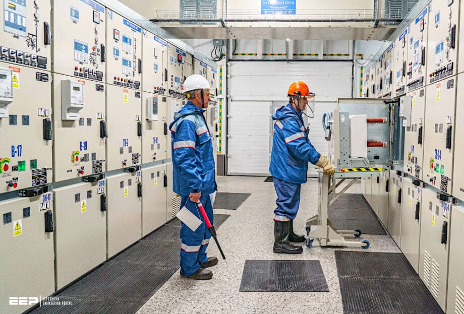
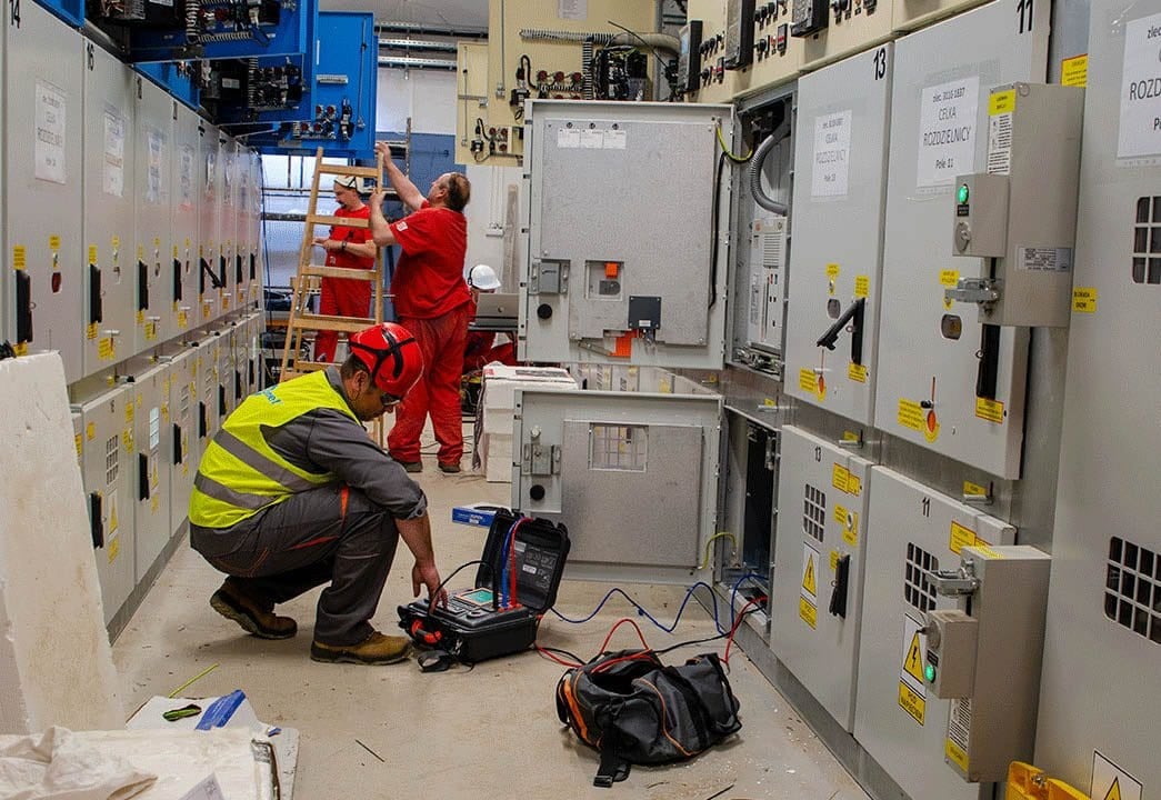
Figure 6 – Engineers performing testing of MV switchgear
2.2 Applying Earths
2.2.1 Portable Earths
Each set of earths to be applied requires the following activities.
- Inspect the portable earth leads and connections to ensure they are in good working order and appropriately rated.
- Layout the portable earths on the ground at the location where the earths are to be applied.
- Connect the main earth to the appropriate earthing point:
- inside substations use the earth studs on the structures which are connected the main earth grid
- outside substations a spike is driven in the ground a minimum of 600mm in the pole alignment, usually one pole from the work site.
- Prove de-energised at the location the earths are to be applied.
- Remain clear of the earth leads and apply to each phase earth with a positive action. Ensure the phase connections are firmly made and the clamps are tight.
Related electrical guides & articles


Edvard Csanyi
Hi, I'm an electrical engineer, programmer and founder of EEP - Electrical Engineering Portal. I worked twelve years at Schneider Electric in the position of technical support for low- and medium-voltage projects and the design of busbar trunking systems.I'm highly specialized in the design of LV/MV switchgear and low-voltage, high-power busbar trunking (<6300A) in substations, commercial buildings and industry facilities. I'm also a professional in AutoCAD programming.
Profile: Edvard Csanyi