
If It’s Not Broken, Don’t Fix It
The aging process starts the moment new substation equipment is put into service; how quickly it happens depends on a number of factors, including the equipment’s use, the environment, the quality of maintenance, and many more. However, things aren’t the same anymore. Digital substation equipment changed the game, and as it appears so far, such equipment will likely last much shorter than old analogue devices. Simply, electronics cannot last that long.
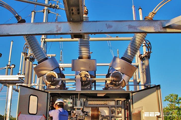
 Substation Equipment Maintenance: Often Neglected Until Something Big Drops Dead (photo credit: Warna RS Sdn. Bhd.)
However, this is yet to be discussed in the coming years. This article tackles electrical substation equipment in general. Although some electrical power equipment has been in use for decades, the majority of it has already degraded to varying degrees.
Having knowledge about several methods to prolong the life of electrical substation equipment becomes crucial the moment its performance starts to deteriorate. Refilling, retrofitting, or rebuilding old electrical equipment typically involves replacing either individual parts or the entire machine with brand new ones.
However, there is an ongoing, reasonable, and cost-effective method of ensuring that the equipment is in good working order by performing timely, comprehensive, and educated maintenance.
The optimal strategy for extending the equipment’s life is to begin as soon as the manufacturer recommends following installation.
In order to keep electrical equipment running for a longer period of time, this technical article presents several methods for maintaining it.
- Different Maintenance Approaches: Corrective, Time-Based (Periodic), Predictive, Condition-Based or Reliability-Centered?
- Maintenance as a Method to Prolong the Lifespan:
- Periodic Lubrication Of Circuit Breakers
- Refurbishment Or Reconditioning of a Circuit Breaker
- Condition-Based Maintennce (CBM):
- BONUS (PDF) 🔗 Download Complete MV Switchgear Wiring Diagrams and Front View & Equipment Drawings
1. Different Maintenance Approaches
Corrective, Time-Based (Periodic), Predictive, Condition-Based or Reliability-Centered Maintenance?
A wise saying states, “If it is not broken, don’t fix it.” This principle underpins the most basic approach to maintenance. Restoring operation by repairing or replacing a component in the event of failure is the basis of Corrective Maintenance (CM), which does not include any additional maintenance checks.
When it would be costly to monitor the condition of components while they are in use and the consequence of a failure is small, CM is often the best choice for such facilities. Minor branches of an LV network may be subject to this type of maintenance in distribution systems.
The term “Time-Based Maintenance” (TBM) describes the conventional approach to electric utility maintenance that relies on a predetermined schedule of checks and replacements. Periodic Maintenance (PM) is another name for this type of fixed-interval maintenance.
In addition, TBM can not be cost-effective, which prompted the development of alternative methods to maintain a healthy electrical power supply.
Better judgment on what is needed and when is achieved when equipment maintenance is based on its condition rather than its number of operations or years in service. Taking advantage of the information received from condition monitoring, a new strategy called Condition-Based Maintenance (CBM) was developed as more and more tools were made available for monitoring the physical conditions of equipment.
The strategy’s upkeep is prioritized according to the needs. Evaluation of the equipment’s status through periodic or continuous (online) monitoring forms the basis of CBM tasks. One more moniker for CBM is Predictive Maintenance (PdM).
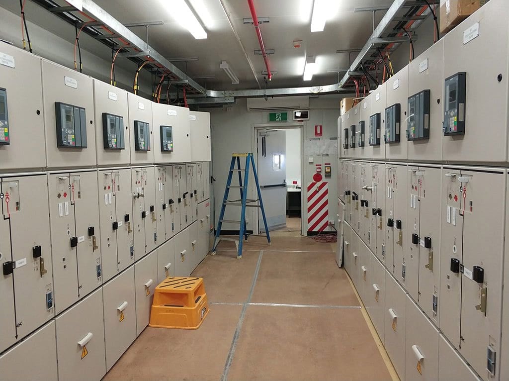
Figure 1 – Scheduled maintenance of medium voltage switchgear

Scheduled maintenance at the most cost-effective time, just before equipment loses performance or fails, is the ultimate goal of CBM/PdM. This differs from TBM, in which equipment is serviced regardless of whether it need repair or not. Aiming to forecast the trend of the equipment’s condition in the future is where the “predictive” part of PdM comes from.
This method finds the optimal future time to do maintenance by applying the concepts of statistical process control. The majority of PdM inspections are carried out while the equipment is in operation, which helps to keep the system running smoothly with minimal interruption.
Increased system reliability and significant cost savings are two potential outcomes of PdM adoption.
Another kind of maintenance technique called Reliability-Centered Maintenance (RCM) is developed when the component’s condition is linked with the component’s functional importance. Because RCM is not a monolithic approach, it enables the comparison of several maintenance methods, allowing for the selection of the most cost-effective one without sacrificing reliability.
It is also possible to view RCM as a process that optimizes the function of other maintenance strategies, such as CM, TBM, and CBM. Better outage scheduling, operational flexibility, spare component management efficiency, and more can all be achieved with PdM. Additionally, RCM assesses the fallout from a failure.
At the system level, RCM is responsible for balancing maintenance expense with its impact on performance. Maximizing the result in terms of system dependability or outage cost reduction is usually the goal.
As part of RCM, distribution networks must first determine which system levels are most important from a reliability perspective, and then choose appropriate methods for each level.
Useful Reading – How to prepare for inspection & testing of MV switchgear
Prepare yourself for successful inspection and testing of MV metal-clad switchgear
2. Maintenance as a Method to Prolong the Lifespan
2.1 Time-Based Maintenance (TBM)
When it comes to maintaining the condition of electrical equipment, TBM (or PM) is still among the most popular methods. There is typically a maintenance section in original equipment manufacturer (OEM) user manuals that specifies how often certain tasks need to be performed. As an example, comprehensive maintenance instructions are provided by all top-tier switchgear manufacturers.
Following these suggestions for maintenance will ensure that your switchgear lasts for more than 40 years. The significance of maintenance is frequently disregarded until a catastrophic breakdown happens, which is far too late. Not knowing enough about the product or not having enough money are two reasons why maintenance is either nonexistent or done poorly.
Main substation switchgear and primary transformers are two examples of crucial system components that typically undergo TBM.
The report from the IEEE/PES task force on the impact of maintenance strategy on dependability, reliability, risk, and probability applications subcommittee, published in the IEEE Transactions on Power Systems, 16(4), 638-646, November 2001, details the recommended maintenance intervals for several critical components.
Table 1 – Reported most frequent maintenance intervals and durations
| Generators | Transformers | Circuit Breakers | ||||
| Interval | Duration | Interval | Duration | Interval | Duration | |
| Minor maintenance | 1 yr | 1-2 wk | 1 yr | 1 day | 1 yr | 1 day |
| Minor overhaul | 5 yr | 4-5 wk | 5 yr | 3 days | 5 yr | 3 days |
| Major overhaul | 8-10 yr | 6-8 wk | 7 yr | 4-8 wk | 8-10 yr | 2 wk |
For instance, CBs and transformers should be serviced once a year at the very least; a minor overhaul should be carried out every five years; and a major overhaul should be carried out once every seven years for transformers and every eight to ten years for CBs. There are always a lot of tests in PM.
Suggested Reading – The good and bad practices in the commissioning of current transformers in a substation
The good and bad practices in the commissioning of current transformers in a substation
2.2 Maintenance Of Power Circuit Breakers
2.2.1 Molded Case Circuit Breakers (MCCBs)
While MCCBs are typically designed to have little to no maintenance needs over their lifetime, it is important to give special attention to MCCB maintenance due to the need of MCCBs for routine switching and other equipment protection.
Failure of an MCCB to operate due to an absence of periodic or preventative maintenance can cause equipment destruction and electric transmission system breakups. It is not always easy to tell when a CB needs maintenance because they might sit open or closed for a long time without doing anything.
To ensure appropriate operation and to eliminate any buildup of dust or foreign material on moving components and contacts, breakers that sit inactive for six months or longer should be set to open and close multiple times in succession.
Taking the breaker out of operation and testing its overcurrent and short-circuit tripping capabilities is the only method to exercise all of its operating and tripping mechanisms. In the event of a malfunction, a stiff or sticky mechanism may inadvertently introduce a delay in its operation.
Figure 2 – Molded Case Circuit Breaker (MCCB), type NSX by Schneider Electric

2.2.2 Low-Voltage Circuit Breakers
It is recommended to examine and maintain low-voltage circuit breakers that operate at 600 VAC or lower every one to three years, subject to their service and operating conditions. In environments with high humidity, high ambient temperature, dust, grime, or corrosion, LV CBs require more regular inspections and maintenance.
Equipment that is older or has breakers that give fault or switching operations more frequently also needs maintenance more often. Whenever a breaker experiences interrupted current at or near its rated capacity, it is important to assess it and perform necessary maintenance. When servicing LV air CBs, be sure to adhere according to the manufacturer’s instructions, which will typically outline general methods. A thorough inspection of the breakers is required.
Be sure to follow the OEM’s instructions to the letter while cleaning and adjusting insulating parts, such as bushings, and when checking and adjusting the condition and alignment of the movable and stationary contacts.
Suggested Course – Circuit Breaker Schematics and Control Wiring Diagrams
Learn to Read and Analyze Circuit Breaker Schematics and Control Wiring Diagrams
2.2.3 Medium-Voltage Circuit Breakers
Different technologies allow for a wide variety of MV CBs; for example, some use live tank technology with vacuum, air, oil, or SF6 as the interrupting media, while others use dead tank technology with oil or SF6 as the media, and so on. For HV CBs, the same holds true. It is recommended to inspect and service MV CBs that operate between 600 and 15,000 V once a year or after 2000 operations, whichever occurs first.
In order to get the desired performance out of the breakers, the relevant standards suggest this maintenance program. You can find all the information you need about how to properly maintain your MV air CB in the owner’s manual. In it, you’ll find detailed instructions for cleaning and lubricating the operating mechanism, as well as for inspecting and adjusting the moveable and stationary contacts in accordance with manufacturer’s data and for cleaning and lubricating the insulating parts, including the bushings.
It is recommended to replace worn parts.
Suggested Video – SF6 circuit breaker maintenance and cleaning
When servicing motor oil circuit breakers (OCBs), it is necessary to clean the tank and any other components that came into touch with the oil. Testing the oil’s dielectric strength—the highest voltage that can be applied across a fluid without causing electrical breakdown—is a crucial component of oil-filled MV breakers.
It is necessary to filter or replace the oil if the voltage is lower than 22 kV. Even if the dielectric strength is fine, if a visual check reveals an excessive amount of carbon, the oil should be filtered or changed.
To avoid oil leaks, it is crucial to check that the gaskets are in good condition and that all nuts and valves are securely fastened during these procedures.
2.2.4 High-Voltage Circuit Breakers
Between six and twelve months is the typical recommendation from most manufacturers for both exterior and interior checks. Internal inspections may not be necessary as often if appropriate external checks are conducted. It is important to base the inspection schedule on the breaker’s interrupting duty.
After the first major disruption caused by a malfunction, it is advised to conduct a thorough internal inspection. Assuming everything is in order on the inside, it’s possible to gradually increase the number of fault interruptions before conducting an inspection. Based on past experiences, high voltage CBs (HV CBs) rated at 230 kV or more can withstand up to five fault interruptions between inspections, while CBs rated at less than 230 kV can manage up to ten fault interruptions.
The standard intervals for both external and interior inspections are 2 and 4 years, respectively.
Interrupter components or barriers have a propensity to burn or degrade, among other problems. There are a number of problems that might arise from using bushing gaskets, one of which being the possibility of water leaking into the breaker insulating material.
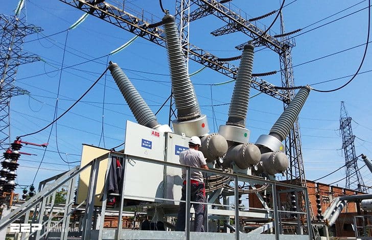
Figure 3 – Maintenance of high-voltage 135kV circuit breaker
2.2.5 SF6-Gas Circuit Breakers
Human sensitivity to SF6 gas determines some upkeep concerns. Even though SF6 gas is harmless when it’s pure, it can stifle breathing by blocking oxygen. Oxygen deprivation can happen suddenly if the typical atmospheric oxygen level drops from 21% to less than 13%.
Hence, after opening CB tanks, they should be emptied. When sulfur 6 gas is exposed to an electric arc, it forms toxic byproducts of its breakdown. White or tan powder is formed by the breakdown products, which are metal fluorides. When solid arc products come into touch with skin, they have the potential to irritate it or even cause a painful fluoride burn.
Hence, it is imperative that maintenance personnel remove all solid SF6 degradation products and avoid breathing in any lingering fumes from a breaker where arcing or corona discharges have occurred in the gas. Before working on the circuit breaker, make sure to remove and flush the faulty SF6 gas from the circuit breaker.
Interesting Reading – Three abnormal situations leading to an uncontrolled release of SF6 gas
Three abnormal situations leading to an uncontrolled release of SF6 gas
3. Periodic Lubrication Of Circuit Breakers
The working mechanism of nearly all power circuit breakers needs maintenance from time to time. Lubrication renewal frequency is determined by a number of criteria. These include the CB’s operational environment, the number of close-open operations since the last renewal, the period that has passed since the last renewal, and the CB’s continuous current rating.
According to IEEE Standard C37.16, an LV power CB must be able to complete a certain number of close-open operations before it needs to be serviced. After a certain number of operations, the lubrication in a CB’s mechanism needs to be replaced according to the specification.
A 500-or 1750-operation count might never occur during the lifetime of a breaker if it only operates a few of times annually. Because all lubrication materials degrade when exposed to air, the need to replenish lubrication remains. Environmental factors, including high air temperatures or the presence of airborne pollutants, hasten this degradation.
Old But Good Video – HV circuit breaker maintenance
The majority of users set the apps to run at predetermined intervals to lubricate important CBs. Lubrication failure has been found to be the cause of malfunctions in CBs with as few as five years of typical use. The OEM user handbook will normally specify the lubricating places that need important attention, so make sure to follow those instructions.
The HV CB operating mechanism’s bearing surfaces should be lubricated according to the manufacturer’s instructions; however, it is important not to lubricate the surfaces to the point where they get too stiff in cold weather from collecting dust and grit, since this might lead to excessive friction.
Lubricating a CB’s mechanism can be done with a wide range of materials. It is possible for a single mechanism to employ multiple types of lubricant at various stages.
Also, the lubricant that was originally placed at the factory may not be the same as what is recommended for renewal. To avoid incompatibilities, be sure to use the material stated in the OEM handbook of a CB. Periodic lubrication is also necessary for components that transmit current, and original equipment manufacturers (OEMs) define lubrication and provide items for it in their user manuals. The main contacts, clusters of primary-circuit fingers, and bus studs are the parts of a circuit breaker that convey the current.
One crucial requirement is to exercise the mechanism as much as possible to preserve the lubricant in optimal functioning condition. This is because lubricants tend to harden and deteriorate with time, and many varieties of CBs do not operate regularly. Dried lubrication is the most common cause of the CB not opening, but this will stop that from happening.
Good Video – Know more risk: Circuit breaker maintenance
4. Refurbishment Or Reconditioning of a Circuit Breaker
When reconditioning a faulty breaker, it is necessary to disassemble it down to its component level. This includes the racking mechanism, operating mechanism, frame, all electrical components, and parts that carry electricity. At the outset of this process, make sure that all of the parts have been examined and tested. Lubricate all parts according to the specifications in the OEM user handbook after a thorough and part-specific cleaning.
Many different options for safety and life cycle management have been created by MV switchgear manufacturers to assist customers in finding the optimum equipment for their needs. Customers are better able to choose a solution that aligns with the plant’s overall business strategy when they have more options, each with its own set of pros and cons.
One option is to rehabilitate the current switchgear, which entails giving it a complete overhaul and returning it to “as new” state. The switchgear is retrofitted when it is determined that one or more of its primary components are worn. Parts that are most likely to break or require frequent maintenance might be singled out for repair. Customers can extend the life of their equipment at a minimal cost by combining these two solutions for MV switchgear.
Watch Video – Repair of 2000A air circuit breaker
Customers that aren’t in a rush to upgrade but yet want decent performance over the next few years may find this choice appealing. There are two main approaches to refurbishing switchgear:
- Focusing on the individual switching devices, and
- Restoring the entire panel.
It is common practice to refurbish switching devices like CBs, contactors, and switches. In order to ensure a constant supply, the devices are taken out of the switchgear and sent back to the maker. Each breaker is taken apart to its component parts in order to restore it. Bearings, cotter pins, and a few other parts are usually swapped out entirely. Every other component is examined carefully for signs of wear and damage, and any necessary replacements are made. We clean and, if necessary, plat each component.
To bring the breaker up to date with the latest production standards, we incorporate product advancements that have emerged since its original construction. A reconditioned breaker gets a fresh start and a brand new guarantee the moment it leaves the factory.
Suggested Course – Mastering Power Substations: Electrical Equipment, Busbar Schemes and Relay Protection
Mastering Power Substations: Electrical Equipment, Busbar Schemes and Relay Protection
5. Condition-Based Maintennce (CBM)
A research carried out in the 1960s with the purpose of developing a preventative maintenance program for the airplane Boeing 747 demonstrated the necessity of conducting CBM using appropriate condition monitoring equipment. The goal of the research was to identify the factors that cause airplane parts to fail. Only 11% of the components exhibited obvious signs of age that would permit a planned overhaul, often known as programmed preventive maintenance. It was determined that 89% of the components lacked these aging signs, ruling out scheduled overhauls as a possible cause of their failure.
In the industrial sector, similar conditional probability curves have been found, revealing that, even with increasing complexity and sophistication, only 30% of components exhibit obvious aging signs.
Based on the condition Preventative maintenance that takes place as a result of monitoring performance and/or parameters is known as maintenance. Consequently, CBM is a method for maintenance that employs condition monitoring to track conditions over time and use the data to determine if maintenance is necessary.
If there is a problem with the monitored item, the severity of the problem, and the time to failure can be determined by performing condition-based maintenance procedures. Finding the source of the degradation and determining which parts of the goods are deteriorating are other functions of CBM jobs.
Figure 4 – Condition-based maintenance could potentially avoid fatal failure and burning of transformers

5.1 High-Voltage Switchgear
Condition maintenance strategies incorporated the creation of new comprehensive diagnostics for HV equipment. The use of CBM technology encompasses both measuring and maintenance tasks. To lessen the financial burden of maintenance without compromising the technical state of the switchgear, one method employs HV switchgear CBM.
To do this, all measurement and maintenance efforts must be directed towards the most important parts.
When dealing with very old switchgear that has a high failure frequency, high current maintenance costs, and long outage times for maintenance, the CBM strategy becomes much more beneficial. Indirect advantages of the CBM method include prolonging the life of equipment through trend analysis of condition data and using data on measured physical conditions as evidence in cases of culpability.
Reducing maintenance operations, total outage time, and cost per switchgear bay is possible with a broad assessment of aging characteristics and methods to control them. By optimizing the monitoring and maintenance program and analyzing the stored condition data, additional cost reductions may be possible.
Contrarily, CBM, software applications, higher engineering operations, and additional measurement equipment all lead to additional expenses. The total number of switchgear participated in the CBM program may provide a significant decrease in the expenses per switchgear.
Figure 5 – Condition-based maintenance of high voltage circuit breakers
5.2 Medium-Voltage Switchgear (Case Study)
The Case of Multiple Violent Thermal Failures On Main Breakers
Let ‘s describe the following case: The Wireless Temperature Monitoring System has been installed at one of the power plants at a large utility (see Figure 6), which suffered multiple violent thermal failures on main breakers. The goal was to use the temperature sensors to continuously monitor temperature while the breakers are under load.
The stand-alone system is able to provide warning alarms as soon as the temperature of the points where sensors are installed reaches a pre-determined level.
Figure 6 – Metal-clad medium voltage switchgear with temperature monitoring system installed at power plant
Wireless temperature sensors have the following parameters:
- Uniquely identified sensing units are built from miniature and dielectric components and operate in direct contact with the surface;
- Sensors are calibrated in wide temperature range: from -0 °C to 150 °C (for outdoor applications sensors arecalibrated from -40 °C to 85 °C);
- Transmittance intervals are based on the rate of a temperature change: signal is sent every minute at temperature rising for 3 °C per minute and once in 3 minutes at stable temperature (battery life saving mode);
- Sensing units use a small coin battery as a power source; minimum battery life 5 years, typical 7-10 years, easily changeable.
Miniature wireless sensors have been installed at all six Finger Clusters (see Figure 7) of four MV circuit breakers, two of which (main breakers) are continuously under load. Two other breakers are used as reserve. Every cell is also equipped with a sensor on the internal wall to measure temperature of the ambient air within the cell. One reading device installed in the control room receives RF signals with information about the location and temperature of each point where the sensors are installed (there are a total of 28 transmitters).
Figure 7 – Wireless temperature sensors installed on circuit breaker’s finger clusters

This information is continuously transferred from the wireless sensor to the local PC located in the operator room and connected with a reading device via communication cable. The temperature data is continuously collected in the database and analyzed together with load data to determine any abnormalities in temperature behavior.
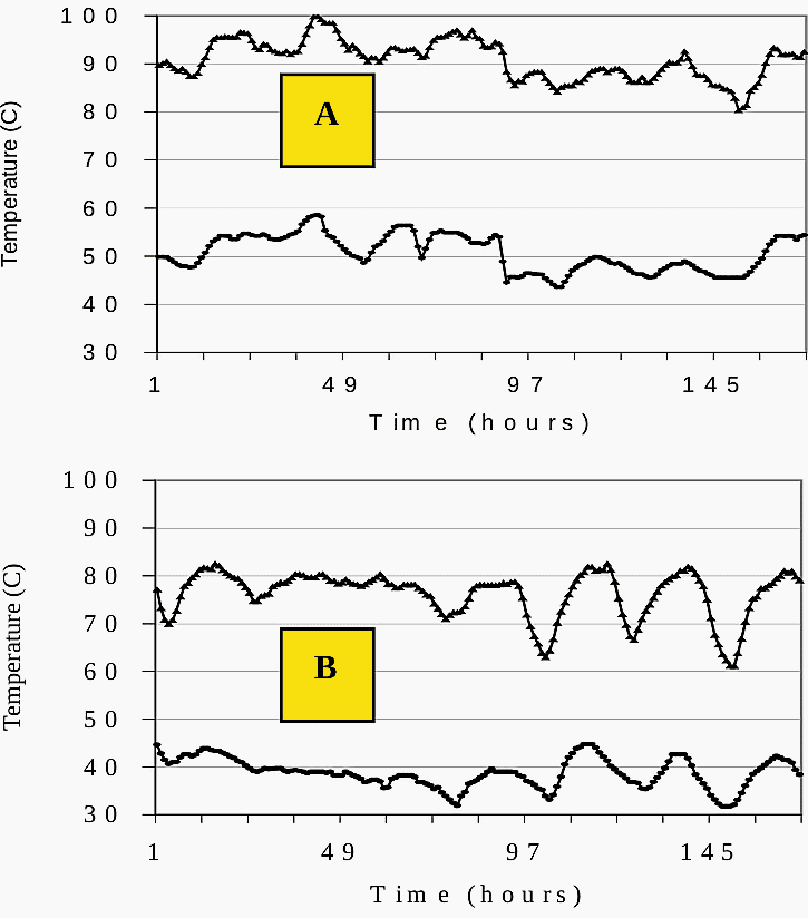
Through two years of temperature monitoring and data analysis, the normal heat distribution within the cell and temperature of finger clusters (depending on the location within the cell) was determined. The change of finger cluster temperature (see Figure 8A) follows every increase and decrease of the current (see Figure 8B) with very short delay (minutes). The shape of the temperature curve is very similar to that of the load, copying even minor changes of the current.
The temperature of the top and bottom FCs on Phase A and C are very close. The difference in temperature between Phase B and Phases A and C is usually in the range 5-10 °C.
Figure 8 – Temperature (A) on Top FC of Phase A (bottom curve) and B (top curve) and Load (B)

After one month of monitoring, the first warning signal was an observation of a very high temperature of the ambient air within the main cells. It was reaching 60 °C even though the current was well below the maximum rated current for the breakers. As a result, the temperature on the finger clusters occasionally reached 100 °C, which is very close to standard maximum for current-carrying parts of MV circuit breakers (105 °C). See Figure 9A.
It was determined that the elevated temperature within the cells was caused by a poor ability to evacuate heat build-up. The existing switchgear did not provide louvers on the doors and no forced ventilation within the cells.
See Figure 9B.
Figure 9 – Ambient temperature (bottom curve) and on B Phase Top FC (top curve) in the same cell without ventilation (A) and with forced ventilation (B)
This drop in temperature provided a large and safe temperature margin for the load on the main circuit breakers.
After one year of data collection and data analyzing, a very unusual abnormality has been detected on one of the phases. The temperature has suddenly risen 10-15 °C on Phase A’s finger clusters and they become as hot (or hotter) as the FCs on Phase B. The temperature rise usually happened when the load rose (see Figure 10).
Six such events have been observed on one main breaker during one year of temperature monitoring. Duration of the rise varied from 40 to 400 hours. Since temperature rises have been within standard limit (less than 65 °C) during these events, the Temperature Monitoring System issued no alarms.
Figure 10 – Temperature growth on Phase A (1) compared with that on Phase B (2) and current (3)

This thermal event on one of the phases affected heat distribution within the cell, leading to significant deviations from normal thermal behavior. The temperature rise on Phase A is accompanied with temperature change on Phase C (see Figure 11), so the top FC becomes warmer than the bottom FC, which is opposite to normal temperature distribution within the cell.
The cause of these temperature abnormalities is not yet determined. Plant personnel have been warned about these events and asked to perform inspection of the unit at the
earliest convenience.
In this case, online continuous monitoring of the temperature of current-carrying parts allowed to avoid thermal failure of the breakers, saving significant assets, and provided justified maintenance activity, which is the meaning and goal of CBM.
Figure 11 – Thermal abnormality on Phase A effects heat distribution within the cell

7. BONUS: MV Switchgear Wiring Diagrams and Front View & Equipment Drawings (PDF)
Download MV Switchgear Wiring Diagrams and Front View & Equipment Drawings (PDF, 68 pages, 780 KB) (for premium members only):
References:
- Transmission, Distribution, and Renewable Energy Generation Power Equipment – Aging and Life Extension Techniques by Bella H. Chudnovsky
- On-Line Condition Monitoring and Diagnostics of Power Distribution Equipment by Albert Livshitz, Member, IEEE, Dr. Bella H. Chudnovsky, Member, IEEE, and Boris Bukengolts Schneider Electric/Square D
Related electrical guides & articles


Edvard Csanyi
Hi, I'm an electrical engineer, programmer and founder of EEP - Electrical Engineering Portal. I worked twelve years at Schneider Electric in the position of technical support for low- and medium-voltage projects and the design of busbar trunking systems.I'm highly specialized in the design of LV/MV switchgear and low-voltage, high-power busbar trunking (<6300A) in substations, commercial buildings and industry facilities. I'm also a professional in AutoCAD programming.
Profile: Edvard Csanyi
