
Standby power supply & outages
The cost of a standby power system for a business can be pretty high, so it’s essential to weigh all of your options before committing to a piece of equipment. The direct and indirect costs must be clearly and unequivocally defined and suitably weighted by management. As always, a distinction must be made between emergency and standby power sources.
 Standby power supply options
Strictly speaking, emergency systems supply circuits legally designated as being essential for safety to life and property. Standby power systems are used to keep a facility from losing production due to a power outage from a utility company.
Many commercial/industrial buildings rely on two independent utility services or one utility service plus on-site generating to assure AC power supply continuity.
Because of the growing complexity of electrical systems, a special attention must be given to power-supply reliability.
- Standby Power System in General
- Dual-Feeder Power Supply System
- Peak Power Shaving
- Advanced System Protection
- How to Choose a Generator?
- UPS Systems
- Batteries
1. Standby Power System in General
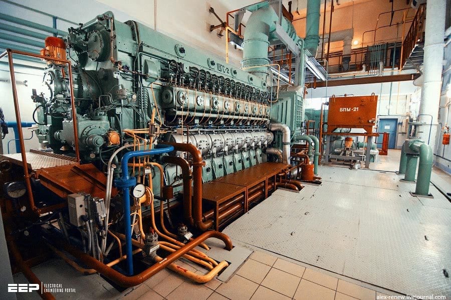
Figure 1 depicts a traditional standby power system with an engine and generator. In the event of a power outage, an automated transfer switch checks the AC voltage coming from the utility company line. The standby generator is started when an outage is detected for a predetermined amount of time (usually 1 to 10s); once the generator is up to speed, the load is transferred from the utility to the local generator.
The load is switched back on and the generator is turned off when the utility supply is restored.
The transfer device shown in Figure 1 is a contactor-type, break-before-make unit. This system protects a facility from prolonged utility company power failures.
Figure 1 – The classic standby power system using an engine-generator set
By replacing the simple transfer device shown with an automatic overlap (static) transfer switch, as shown in Figure 2, additional functionality can be gained. The overlap transfer switch permits the on-site generator to be synchronized with the load, making a clean switch from one energy source to another.
This functionality offers the following benefits:
- Switching back to the utility feed from the generator can be accomplished without interruption in service.
- The load can be cleanly switched from the utility to the generator in anticipation of utility line problems (such as an approaching severe storm).
- The load can be switched to and from the generator to accomplish load shedding objectives.
Figure 2 – The use of a static transfer switch to transfer the load from the utility company to the on-site generator

Go back to the Contents Table ↑
2. Dual-Feeder Power Supply System
In some urban areas, usually in big cities, two utility power connections can be brought into a facility as a means of providing a source of standby power. As shown in Figure 3, two separate utility service connections (from separate power-distribution systems) are brought into the plant, and an automatic transfer switch changes the load to the backup line in the event of a main-line failure.
The dual-feeder system provides an advantage over the auxiliary diesel arrangement in that power transfer from main to standby can be made in a fraction of a second if a static transfer switch is used. Time delays are involved in the diesel generator system that limit its usefulness to power failures lasting more than several minutes.
The downside of the dual-feeder system is that it’s limited primarily to urban areas. Rural or mountainous regions generally are not equipped for dual redundant utility company operation. Even in urban areas, the cost of bringing a second power line into a facility can be extremely high, particularly if special lines must be installed for the feed.
Figure 3 – The dual-utility-feeder system of AC power loss protection. An automatic transfer switch changes the load from the main utility line to the standby line in the event of a power interruption

If two separate utility services are available at or near the site, redundant feeds generally will be less expensive than engine-driven generators of equivalent capacity. Figure 4 illustrates a dual-feeder system that utilizes both utility inputs simultaneously at the facility.
Notice that both AC lines feed loads during normal operation, and the “tie” circuit breaker is open. In the event of a loss of either line, the circuit-breaker switches reconfigure the load to place the entire facility on the single remaining AC feed.
Switching is performed automatically; manual control is provided in the event of a planned shutdown on one of the lines.
Figure 4 – A dual-utility-feeder system with interlocked circuit breakers

Go back to the Contents Table ↑
3. Peak Power Shaving
Figure 5 illustrates the use of a backup diesel generator for both standby power and peak power shaving applications. Commercial power customers often can realize substantial savings on utility company bills by reducing their energy demand during certain hours of the day. An automatic overlap transfer switch is used to change the load from the utility company system to the local diesel generator.
The changeover is accomplished by a static transfer switch that does not disturb the operation of load equipment.
The automatic overlap (static) transfer switch changes the load from the utility feed to the generator instantly so that no disruption of normal operation is encountered.
Figure 5 – The use of a diesel generator for standby power and peak power shaving applications

Go back to the Contents Table ↑
4. Advanced System Protection
A more sophisticated power-control system is shown in Figure 6, where a dual feeder supply is coupled with a motor-generator set to provide clean, undisturbed AC power to the load. The M-G set (motor-generator set) will smooth over the transition from the main utility feed to the standby, often making a commercial power failure unnoticed by on-site personnel.
A conventional M-G set typically will give up to 0.5 s of power fail ride-through, more than enough to accomplish a transfer from one utility feed to the other. Switching circuits allow the M-G set to be bypassed, if necessary.
Related electrical guides & articles


Edvard Csanyi
Hi, I'm an electrical engineer, programmer and founder of EEP - Electrical Engineering Portal. I worked twelve years at Schneider Electric in the position of technical support for low- and medium-voltage projects and the design of busbar trunking systems.I'm highly specialized in the design of LV/MV switchgear and low-voltage, high-power busbar trunking (<6300A) in substations, commercial buildings and industry facilities. I'm also a professional in AutoCAD programming.
Profile: Edvard Csanyi
