Communication circuits
Communication systems of electric utilities have become increasingly critical to electric system protection, operation, and maintenance. For fast tripping and clearing of system faults, communication-aided relaying has become a common protection scheme, particularly in line protection.

Control centers depend on reliable communication channels to remotely operate substation circuit breakers and switches, telemeter electrical quantities of the electric system, and monitor substation alarms.
Maintenance engineering has also become increasingly dependent on communications for remote access to intelligent electronic devices such as relays, remote terminal units, digital fault recorders, and revenue meters.
The area of communication can be split into three areas:
- Internal communications: the communication system design internal to the substation that feeds into the external communications and documents relay-to-relay communications;
- SCADA: details of the documentation unique to SCADA data; and
- External communications: inter-substation communications and the details of the communication media used.
Note that these three areas of communication are all integrated with each other, and there is overlap between these areas.
1. Internal Communications
IEEE Std C37.1 discusses the importance of block diagrams, addressing the communication block diagram in more detail. The communication block diagram provides a similar function for the communication system as the substation one line provides for the electrical design.
Before any communication design begins, all of the internal and external connections to IEDs should be put on a drawing.
These circuits include:
- Remote SCADA communications to one or more entities and/or utilities for operational data
- Remote communications to one or more entities and/or utilities for nonoperational data
- Inter-substation protective relay communications via various transport methodologies:
- Dedicated fiber using proprietary communications
- Serial multiplexed signals to a SONET ring
- Power line carrier (PLC)
- Ethernet
- Leased telco circuits
- Radio/microwave circuits
- Local telco circuits for substation phone and/or data circuits
- Revenue metering data circuits
Entities involved for each of these circuits can be one or more utilities, power plants, and independent system operator.
IED Connections
The communication block diagram should detail the following connections for each IED:
- Device designation
- Device part number (optional)
- RS-232 serial communication ports with connector type (terminal block, DB9 male/female) and port number with front or rear indicated as necessary
- RS-485 serial communication ports with connector type (terminal block, DB9 male/female) and port number or terminal block number with front or rear indicated as necessary
- Ethernet ports with connector type and speed (RJ45: 10/100BaseTX, 10/100/1000BaseTX; ST, MTRJ, LC: 10BaseFX, 100BaseFX) and port number with front or rear indicated
- IRIG-B port with connector type (coax, terminal block) and modulation, with a port number or terminal block number with front or rear, indicated as necessary
Device designations can use device number 16 when appropriate. C37.2 added device number 16 to refer to data communications devices and lists suffixes to identify the functions. The first suffix indicates whether the device is serial (S) or Ethernet (E). Subsequent suffixes indicate the following functions: security processing (C), firewall (F), network managed (M), router (R), switch (S), and telephonic (T).
Device designations on the block diagram should match those assigned on nameplates and drawings to provide consistency across the design documentation.
The communication block diagram should connect communications ports together, with cable types indicated by line type and/or line annotation. The organization of the communication block diagram is very important, as the diagram can quickly become a mess of lines that is difficult to read and understand.
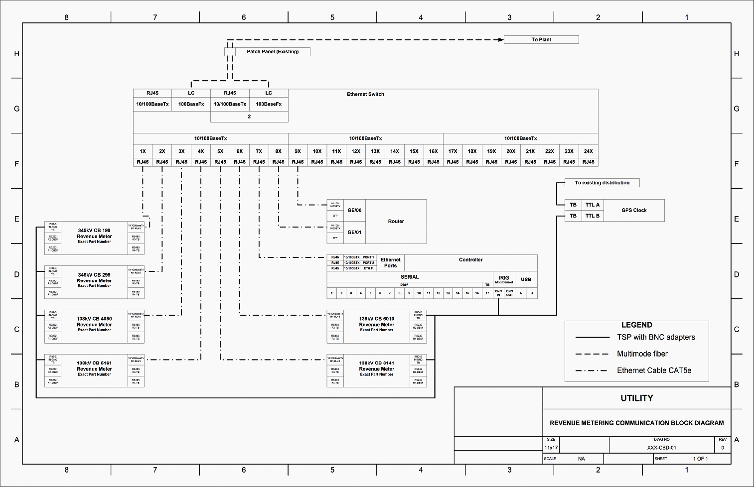
Figures 1, 2, and 3 are examples of block diagrams. Figure 1 shows a small, simple block diagram for a metering system connected to a generation plant with IRIG-B
connections and network connections are shown.
Figure 1 – Example Block Diagram #1 (click to zoom)


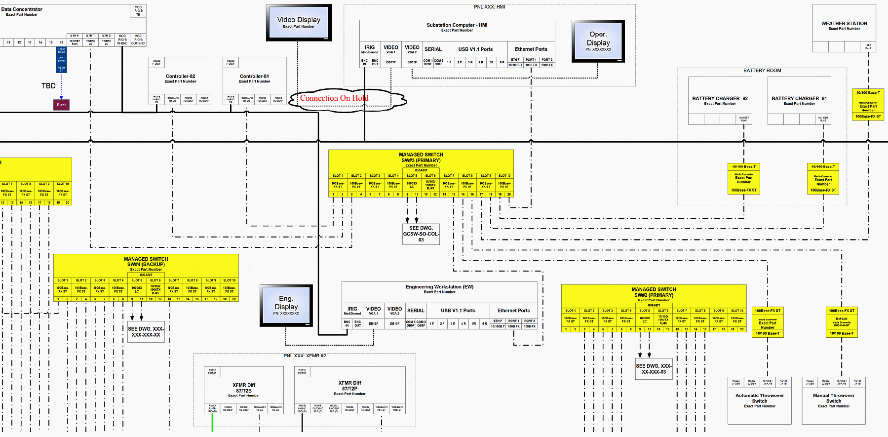
Figure 2 shows a detail from a larger, more complex conceptual block diagram for a complete substation automation system without the IRIG-B distribution shown. This drawing was completed at the conceptual design stage, well before any detailed design was started. Some protective relay communications are shown.
Note the use of device number 16. For example, 16ERFCM indicates an Ethernet router, managed, with a firewall and VPN for cyber-secure communications.
Figure 2 – Detail from Example Block Diagram #2 (click to zoom)


Figure 3 is a detail from an even larger, more complex block diagram for part of a substation automation system that shows IRIG-B distribution. At the point of the design process, Figure 3 had not yet captured the protective relay communication requirements.
Figure 3 – Detail from Example Block Diagram #3 (click to zoom)


Go back to the Contents Table ↑
2. SCADA Documentation
SCADA is an important part of substation control and protection and its integration to protective relay schematic is very common. The SCADA equipment discussed in this
section is referred to as Substation Remote Terminal Unit (RTU).
This section does not cover the SCADA – Energy Management System that is the SCADA master at utility control/operation center.
Membership Upgrade Required
This content is not available in your premium membership plan. Please upgrade your plan in order to access this content. You can choose an annually based Basic, Pro, or Enterprise membership plan. Subscribe and enjoy studying specialized technical articles, online video courses, electrical engineering guides, and papers.
With EEP’s premium membership, you get additional essence that enhances your knowledge and experience in low- medium- and high-voltage engineering fields.
Limited Time Gift! – Save 10% on Pro Membership Plan with code 110VDC
Copyright Notice
This technical article is protected by U.S. and international copyright laws. Reproduction and distribution of PDF version of this technical article to websites such as Linkedin, Scribd, Facebook and others without written permission of the sponsor is illegal and strictly prohibited.© EEP-Electrical Engineering Portal.
Related electrical guides & articles
Premium Membership
Edvard Csanyi
Hi, I'm an electrical engineer, programmer and founder of EEP - Electrical Engineering Portal. I worked twelve years at Schneider Electric in the position of technical support for low- and medium-voltage projects and the design of busbar trunking systems.I'm highly specialized in the design of LV/MV switchgear and low-voltage, high-power busbar trunking (<6300A) in substations, commercial buildings and industry facilities. I'm also a professional in AutoCAD programming.
Profile: Edvard Csanyi


