
Architecture, Voltage Challenges & Protection Coordination
The evolution of power distribution networks is being shaped by unprecedented growth in distributed energy resources (DERs), particularly rooftop solar and other inverter-based technologies. Traditionally designed for one-way power flow from substations to end-users, distribution systems are now experiencing reverse flows, dynamic voltage fluctuations, and increasingly complex protection requirements.
 The Problems of Modern Distribution Systems in the Age of Distributed Energy Resources (DERs)
This article explores the architectural foundations of distribution systems—radial, parallel, and ring main networks—and examines how modern power flow dynamics are reshaping their operation. Special attention is given to voltage rise phenomena under light loading, the dual-function behavior of distribution transformers, and the growing need for advanced grid intelligence.
A major shift underway is the transformation of Distribution Network Operators (DNOs) into Distribution System Operators (DSOs). This transition reflects the necessity for utilities to actively manage power flows, optimize DER integration, and provide visibility and control over network constraints.
We delve into the rationale behind this evolution, the operational differences it entails, and both the benefits and challenges associated with adopting a DSO model.
The article then highlights the broader integration challenges of DERs, from voltage regulation and power quality disturbances to islanding risks, frequency stability, and regulatory shortcomings.
Together, these insights offer a comprehensive look at the changing face of distribution systems and provide practical strategies for navigating the technical and operational challenges of a decentralized energy future.
- Radial Feeders in Distribution Systems
- Parallel Feeders Distribution System
- Ring Main Distribution System
- Direction of Power Flow in Modern Power Distribution Systems:
- From DNO to DSO: The Evolving Role of Distribution Network Operators in the Modern Power System:
- Integration Challenges of Distributed Generation (DG) in Legacy Grids:
- Protection Coordination Challenges in Grids with High Distributed Generation (DG) Penetration:
- Case Example: Protection Coordination in a High-DG Feeder:
- Attachment (PDF) 🔗 Download ‘A Guide to Protection of Electricity Distribution Networks’
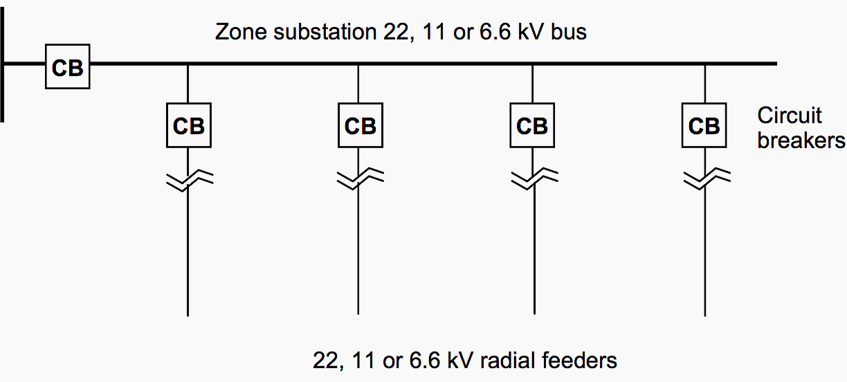
1. Radial Feeders in Distribution Systems
A radial distribution system is one of the most employed configurations in power distribution networks, especially in areas where simplicity and cost-effectiveness are key priorities. This system is typically utilized when the substation or generating station is centrally located relative to the load centers or consumer clusters it serves.
In a radial configuration, each feeder originates from a single point—either a substation or a generating station—and extends outward like spokes of a wheel to supply power to end consumers. These feeders supply electricity to distribution lines or distributors from one end only, with no alternate path for the current to reach the load.
However, this simplicity comes with trade-offs. The lack of redundancy means that any fault or interruption in a feeder typically results in loss of supply to all downstream consumers until the fault is cleared or the line is restored.
Figure 1 – A single-line diagram of a typical radial distribution system is illustrated
2. Parallel Feeders Distribution System
To overcome the key limitation of the radial distribution system—namely its lack of redundancy and vulnerability to single-point failures—a parallel feeders distribution system can be employed. In this configuration, two or more feeders are installed in parallel between the source (such as a substation) and the distribution area.
By introducing parallel feeders, the system enhances reliability and continuity of power supply, as it provides an alternative path for power flow in case one feeder becomes inoperative due to a fault or maintenance.
While this approach significantly improves the resilience and flexibility of the network, it comes at the expense of a higher initial investment, as the number of feeders—and thus the infrastructure cost—is effectively doubled compared to a radial system.
Figure 2 – Parallel Feeders Distribution System

3. Ring Main Distribution System
The ring main distribution system offers a level of reliability and operational flexibility comparable to that of parallel feeders, but with a more economical and compact design. In this configuration, the distribution network forms a closed loop—or “ring”—that begins and ends at the substation busbars.
The key feature of this system is that each distribution transformer is supplied by two distinct paths, ensuring that in the event of a fault or planned maintenance on one section of the ring, the affected transformer can still receive power from the alternate direction.
This enhances supply continuity and minimizes downtime for consumers within the loop.
Although the ring main system is slightly more complex than a simple radial layout, it is less costly than full parallel feeder arrangements while still providing substantial improvements in reliability. For this reason, it is widely used in urban distribution networks, industrial estates, and critical infrastructure zones where supply reliability is a key concern.
Figure 3 – A typical single-line diagram of a ring main distribution system is illustrated in the figure

4. Direction of Power Flow in Modern Power Distribution Systems
Traditionally, power distribution networks, especially those using radial configurations, were designed with a unidirectional flow of electricity, moving from the grid (source) toward the end consumers (load). This conventional model made system design relatively straightforward: parameters such as voltage drops, load current, and fault levels could be easily predicted and calculated during the initial planning stages.
However, with the evolution of the power sector and the global shift toward renewable energy, the dynamics of power distribution have significantly changed.
In this new scenario, power no longer flows in just one direction. Instead, it can flow bidirectionally from the grid to the load, and also from distributed generators back into the grid. This reversal or duality in power flow introduces several new challenges for utilities, engineers, and planners:
4.1 Complexity in Voltage Drop and Fault Calculations
Unlike the traditional model, the presence of multiple generation points makes it difficult to accurately calculate voltage drops, line currents, and short-circuit levels, as the direction and magnitude of current can vary depending on generation and load conditions.
Related electrical guides & articles


Muhammad Kashif
Muhammad Kashif Shamshad is an Electrical Engineer and has more than 17 years of experience in operation & maintenance, erection, testing project management, consultancy, supervision, and commissioning of Power Plant, GIS, and AIS high voltage substations ranging up to 500 kV HVAC & ±660kV HVDC more than ten years experience is with Siemens Saudi Arabia.Profile: Muhammad Kashif
