Engineering SAS Project
The development of the engineering process is crucial in any SAS project. Sometimes it takes longer than expected and in extreme scenarios may put corporate deadlines for accomplishing entire substation projects at risk. There are several main factors that can detrimentally affect the engineering process of SAS project.

 The Most Costly Traps in the Engineering of a Substation Automation System (SAS) (photo credit: Pro Integris via Linkedin )
The most common and at the same time most critical is the uncertain scope and/or technical requirements in the user specification. Every aditional feature inrease the project price and put the project to the limit. Obviously, the consequence of this issue are prolonged discussions to agree a definitive solution.
Consequently there are annoying and costly delays in submitting information.
This technical article intends to help all SAS project actors to carry out the engineering process in an efficient manner.
- Tricky SAS Requirements
- Clear Overview of the Entire SAS:
- Attachment (PDF) 🔗 Download ‘Modern Grid and Substation Automation’
1. Tricky SAS Requirements
The initial SAS requirements are outlined by the substation owner through a combination of formal specification and planning information. Specification covers the technical aspects to be considered for system design while planning information refers to all management premises to be followed to fulfill the project objectives.
Commonly, the scope and depth of SAS technical specification varies significantly from a substation owner to another.
Other extreme cases exhibit an exaggerated level of detail, sometimes including the desired SAS topology. These cases may force SAS suppliers to offer unproven prototype solutions.
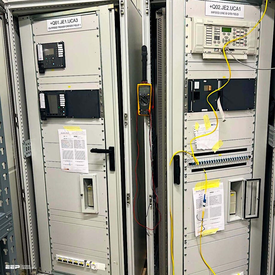
Figure 1 – Substation automation, control and protection panel

2. Clear Overview of the Entire SAS
Having an early, clear overview of the entire prospective system is a key factor in the SAS engineering process. This allows knowledge in advance about the scope of the work to be developed, it is the guide to define what information is needed from both sides and forms the basis for planning different engineering activities.
This step usually concludes with drawing up a detailed and definitive physical topology scheme in which different real devices and the integrated communication network are represented (instead of just a simplified logic topology scheme).
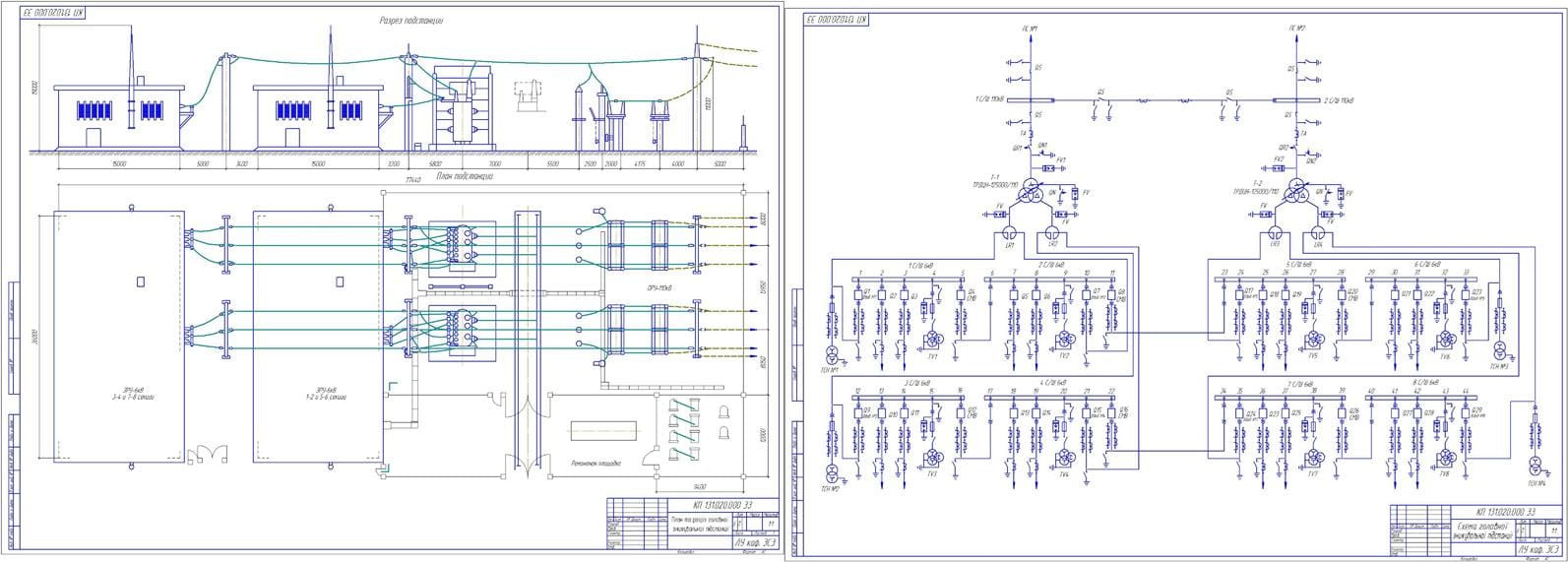
Figure 2 – Single line diagram and physical layout of 220/110/35/10kV substation (click to zoom)
2.1 General Concept of a SAS Project
When SAS projects are contracted in a competition style commercial process, different bidders will offer their simplest, standardized and cheap solutions. Sometimes, the proposed solution comes from a quick interpretation of the user specification written in a foreign language and often such a proposed solution does not include enough information for extensive evaluation by the substation owner.
Once the contract is signed, a clarification stage begins in which the SAS vendor may be surprised by the full set of user expectations, while the user can be disappointed because of the extra cost claimed by the vendor.
At this early stage, typical issues to deal with are the following:
- Number of feeders to be controlled from each bay controller.
- Relationship between control and protection functions.
- Definitive topology.
- Function integration.
- Communication platform.
- Hardware capabilities and functions.
- Application of state‐of‐the‐art solutions.
- List of engineering documents.
Figure 3 – An example of a clear and complete single diagram

2.2 System Topology
An elementary principle in SAS projects is that the substation owner must provide all prospective bidders with the freedom to propose their internally standardized topology, which based on previous experience, can be considered to be best suited to the specific case.
Similarly, the substation owner should check if the proposed topology fulfills its specification.
These capabilities include the following:
- No loss of already acquired but not yet treated data at all control levels.
- Possibility for continued and safe manual control (either from remote terminal, station level or bay level) respecting all the interlocking conditions and procedures.
- Possibility of continuing system operation without endangering personnel and equipment (certain degradation in the operation comfort such as automatic operation may be acceptable).
- Capability to keep the remote control safe from the Network control center (NCC), even if the substation is unmanned.
- Capability to make the time stamping task and storage of events continuous until they can be transmitted to higher hierarchical levels.
- Possibility of maintenance and replacement of defective components without the need to shut down the system.
The evaluation of the proposed solution may result in small or significant changes to conform the already mentioned optimized solution.
An example is shown in Figure 4.
Figure 4 – Example of SAS solution evolution

2.3 Clarifying Non‐visible Issues
The scheme of system topology does not necessarily say all that substation owners need to know; rather, in some cases it may create confusion or misunderstanding. Because of that, besides the topology, before starting the detailed system engineering, a lot of non‐visible issues have to be clarified between vendor and buyer in order to avoid inopportune and polemic discussions.
These issues include:
Issue #1 – System performance
Refers to relevant operative features under both normal or emergency conditions, such as:
- Function allocation in different devices.
- Communication process.
- Operation mode of duplicated components.
- Operation possibilities during emergencies.
- Time stamping procedures.
- Power consumptions.
Watch Video – Review of a SAS base design
Issue #2 – Limits of the scope of supply
Interfaces are always gray zones. In cases of SAS projects, particular care must be taken to define early on the party responsible for providing certain facilities, such as A/D converter modules and interface connections for temperatures and tap changer position of power transformers (if SAS vendor or transformer manufacturer).
It is recommended that SAS vendors are responsible for providing the complete set of devices and accessories belonging to the communication path to the Network control center (NCC), including the modem and accessories needed at a remote terminal.
Issue #3 – Control and protection integration
The degree of integration must be clear. A common practice is to keep the protection function autonomous for a HV substation and integrated control and protection functions for voltage levels at and below 36 kV.
Issue #4 – Segregation of IEDs
Traditionally, electrical utilities have a culture of standardization. In that sense, it is recommended to evaluate the advantages and disadvantage of grouping the bay controllers and protective relays to be connected to a common node, for example to a star coupler device.
Segregation criteria may be, for example, based on primary voltage levels or by main and backup units in case of protective relays.
Watch Video – SAS based power substations
Issue #4 – Interface with primary equipment
Even if a hard‐wired means was planned in the user specification, exploration of the benefits of using the IEC 61850 process bus is recommended.
Issue #5 – Redundancies validation
In some cases, any device may have duplicated power supplies but this is arranged in a supplementary manner. It may induce a false perception of redundancy.
Issue #6 – Redundancies possibilities
Further to power supplies, some devices can support redundancies in other active components like the bus master and input/output cards. That possibility may be explored especially for more critical devices, such as star coupler units.
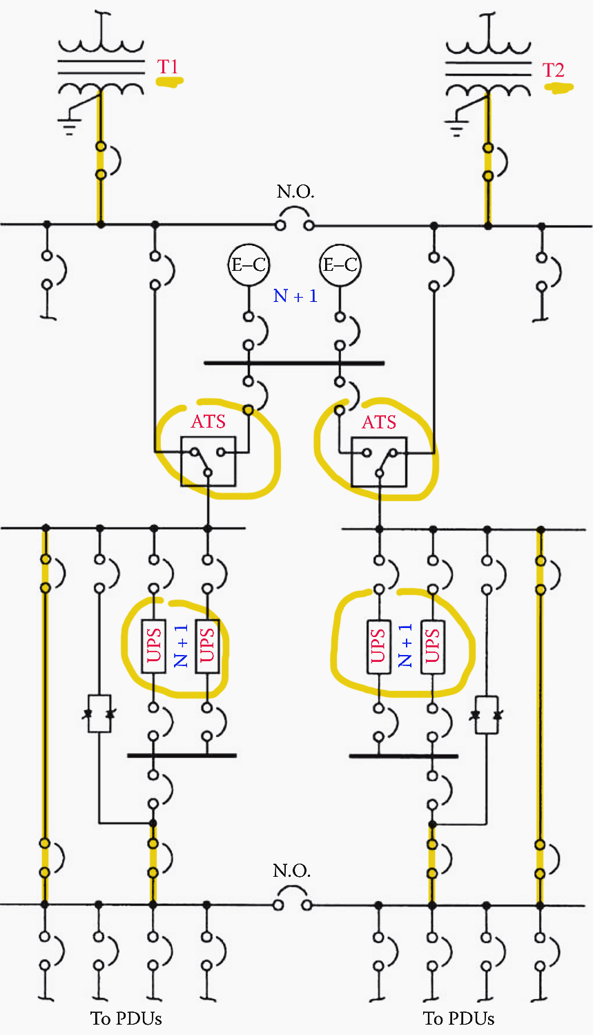
Figure 5 – Power-distribution system featuring redundancy and high reliability
Issue #7 – Inter‐bay interlocking logic
Current technology allows the implementation of this interlocking category through horizontal communication (bay controller–bay controller) by using the GOOSE service defined by Standard IEC 61850.
Although until now only a few practice applications have been reported, it is expected that such means will be commonly applied in the medium term.
Further Study – Interlocking for 380kV GIS Substation: One-and-a-half breaker scheme analysis
Interlocking for 380kV GIS Substation: One-and-a-half breaker scheme analysis
Issue #8 – Measuring allocation
Most IED manufacturers have integrated the measuring and storage in digital form of currents, voltages, active and reactive power values in their protective relays. This is because these values are necessary for performing the protection function and values can be stored easily without any significant extra CPU loading.
This method eliminates the need for cabling the current circuit to the bay controllers, which simplifies the design of the BC bringing the benefits of better security against electromagnetic i nterference and also leading to a reduction of the overall system cost.
In addition, where the protection is duplicated, there are two sets of indications available thus providing redundancy at no additional cost.
Issue #9 – Disturbance recording
By evaluating the attributes of the disturbance recording functionality generally integrated into protective relays, it is possible to confirm if any intended separate disturbance recording system are still justified.
Further Study – Dangerous threats that can compromise operation of modern digital substations and IEDs
Dangerous threats that can compromise operation of modern digital substations and IEDs
Issue #10 – Protocol conversion
This task may be performed by a separate device or as a function of the station controller. The preferred solution must be fixed.
Issue #11 – Communication path to NCC
It may be the case that an end device, which appears be a protocol converter, is in reality a passive component, for example a router or a switch. This happens particularly in cases of redundant station computers.
Issue #12 – Hardware data‐sheet
Both parts (buyer and vendor) need to know the strengths and weakness of different system components. Special care is required to quality check those important components coming from third parties, for example Ethernet switches.
Further Study – Ethernet in substation automation applications – Issues and requirements
Ethernet in substation automation applications – Issues and requirements
Issue #13 – Engineering tools
The information to be exchanged between contracting parties when the engineering process starts includes a list of the engineering tools the vendor will use in the particular SAS project.
Issue #14 – Tests with remote control center
If these tests are foreseen, it is recommended to make a particular point to clarify key related issues like the methodology to be followed and the provider of master station emulator and traffic monitor device.
Watch Video – Local/remote selection OG feeder
Issue #15 – Cubicle identifications
A standardized practice in engineering process consists of establishing early on a series of codes for cubicle identification depending on its functions and the location of the associated primary bay.
The IEC Standard 81346–1 is recommended to define these identification codes.
2.4 Premises for Engineering Work
Before starting the engineering work, the substation owner and vendor/integrator must all agree on a set of symbols, colors and conventions to be used in the particular SAS project.
These include:
Premise #1 – Equipment identification
All switchgear will have a unique identification code based preferentially on user internal standards, for example H2105. Usually, the first character is common to all equipment installed at the same primary voltage level.
Premise #2 – Switchgear symbols and colors
Due to switchgear are changing state equipment, a particular form to represent the actual state on the HMI must be agreed. A way to do that is by filling out a form like that shown in Table 1.
Table 1 – Example of fixing switchgear position/condition indication

Premise #3 – Colors for primary circuits
It is common that utilities distinguish different primary voltages levels by using different colors when drawing the respective single‐line diagrams. Those standardized colors can be agreed filling put a form as shown in Table 2.
Table 2 – Example of form for fixing colors for primary circuits

Premise #4 – Conditions of process objects
The process objects to be loaded in the SAS databases (indications, tasks, devices), may exhibit various conditions based on certain pre‐defined criteria, such as:
- Normal condition: When a preset value falls into an acceptable range.
- Alarm in no acknowledged condition: When a preset value falls out of an acceptable range or a device or subsystem presents an operative problem. The object shows the attributes to call the attention of the substation operator.
- Alarm in acknowledged condition: When a preset value falls out of an acceptable range or a device or subsystem presents an operative problem. The object keeps the signs of abnormal condition but without calling the attention of the substation operator.
- Selected condition: When a device has been marked by the substation operator to carry out a switching procedure.
Premise #5 -Tagging modes
Refers to the facilities give to the substation operator to add advertences or restrictive conditions temporarily on HMI displays. These include the following:
- Manual input: This predefined tag is to be used for shown information unsupervised by the system.
- Operator notes: This is an open type tag to add comments and instructions.
- Control inhibited: When this tag is attached to a specific apparatus symbol, the equipment cannot receive control commands.
- Alarm inhibited: Adding this tag to any process object under alarm conditions means the alarm signal will disappear but the warning of an abnormal condition is still present.
- Apparatus in maintenance: This tag will block the remote operation of the equipment marked.
Learn more – Substation Safety and Switching Rules You MUST Follow
Premise #6 – Attributes of process objects according to condition or tagging
The way process objects should be shown on the HMI under different circumstances must be agreed on, for example filling out a form as in Table 3.
Table 3 – Example of form for fixing attributes of process objects

Premise #7 – Attributes of analog values
The way analog values should be shown on the HMI under different circumstances must be agreed, for example filling a form out as in Table 4.
Table 4 – Example of a form for fixing analogue values attributes

Premise #6 – Attributes of alarms
The way alarms should be shown on the HMI under different circumstances must be agreed, for example filling out a form as in Table 5.
Table 5 – Example of format for fixing alarm attributes

2.5 Checking Signals Lists
Although signals lists have some detractors, they are needed to check that all pertinent signals are considered in the engineering scope and also to agree the alarm and event texts to be displayed at different control levels.
2.5.1 Signals List Related to the Bay Controller
This list contains the signals and their proprieties, as well as the specific point in where they are received by the IED, as is shown in Table 6.
Table 6 – Example of the bay controller signal list

2.5.2 Signals List Related to Bay Controller of the Auxiliary Power System
This is similar to the standard bay controller but refers to the auxiliary system. See Table 7.
Table 7 – Example of the BC auxiliary system signal list

2.5.3 Signals List Related to the Station Controller
This list covers the position indication of all primary and secondary switchgears. See Table 8.
Table 8 – Example of the station controller signal list

2.5.4 Signals List for Communication with the NCC
This list includes all the object information needed at remote control level. See Table 9.
Table 9 – Example of the remote control level signal list

2.5.5 Point to Point Signals List (For Each Bay)
This list shows how signals are displayed along all hierarchical control levels, as shown in Table 10.
Table 10 – Example of a point to point signals list

2.5.6 Signals Lists Related to Equipment and Systems
Samples of signals lists related to equipment and systems are included in Table 11.
Table 11 – Signals List Related to Circuit Breakers (Each One)

Table 12 – Signals List Related to Collateral Devices

Table 13 – Signals List Related to the Auxiliary Power System

Table 14 – Signals List Related to the SAS Itself

3. Attachment (PDF): Modern Grid and Substation Automation
Download: Modern Grid and Substation Automation (for premium members only):
Source: SAS Design by Evelio P.
Related electrical guides & articles


Edvard Csanyi
Hi, I'm an electrical engineer, programmer and founder of EEP - Electrical Engineering Portal. I worked twelve years at Schneider Electric in the position of technical support for low- and medium-voltage projects and the design of busbar trunking systems.I'm highly specialized in the design of LV/MV switchgear and low-voltage, high-power busbar trunking (<6300A) in substations, commercial buildings and industry facilities. I'm also a professional in AutoCAD programming.
Profile: Edvard Csanyi