Transformer Performance Ratings
Assuming that you have a general understanding of transformer parameters and IEC Standards in use, this technical article is aimed at providing a variety of tools and data to make an educated assessment of the principal transformer performance ratings.

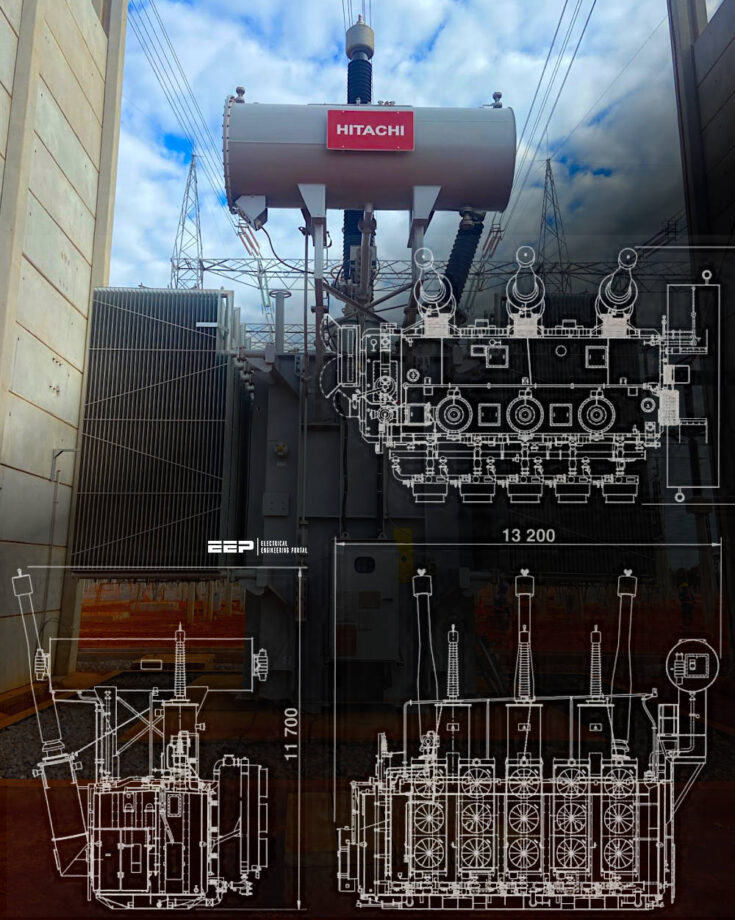 How to estimate transformer performance and characteristics
Derived from transformer design tools, curves, formulae, etc., this technical article should allow the reader to produce a credible estimate of a potential transformer’performances characteristics, including weights ond dimensions, losses, magnetizing currents, relative variations in impedance across the tapping range, and a basic estimation of sound level.
It should be emphasized that this is on educated estimate.
- Sizing Transformer Power Definition:
- Transformer Mass Estimation:
- Transformer Dimensions Estimation:
- Transformer Losses and No-Load Current:
- Transformer Impedances:
- Estimation of Transformer Sound Levels:
- Attachment (PDF) 🔗 Download ‘Transformer Design and Calculations Handbook’
1. Sizing Transformer Power Definition
The prescribed way of defining the throughput capabitity of a transformer is to use the rated power. This rated power is well defined in the standards and is one of the main parameters of sizing a transformer. However, this essential parameter does not always give a clear identification of the physical size of the transformer.
In order to overcome this particular difficulty, it has becomea well known practice in the transformer industry to introduce a sizing power definition, which better determines the physical size of the unit in “Sizing MVA“.
As an initial demonstration of the application, reference is made to the simplest feasible transformer, which has only two windings and neither winding is provided with tappings. In this simple case, the rated power of each of the separate windings is equal to the transformer rated power.
The higher voltage (HV) winding is dimensioned to carry the rated load (Sn MVA) and the same applies to the lower voltage (LV) winding. In other words the transformer has two windings each designed to have the number of turns and conductor cross-sectional area for Sn MVA rated power.
Its Sizing MVA (Ssizing) is defined as half the sum of the rated powers of all windings i.e. (Sn+ Sn)/2 which in this case equals Sn.
Most types of transformers have two or more windings, for example; autotransformers, transformers with a tapping winding, and phase-shifting transformers.
This technical article will givethe basic calculations of the physical transformer sizea nd use this to develop assessments of other parameters for the main types of transformers that are normally encountered.
Watch Lesson – Transformer MVA sizing
1.1 Transformers with More Than Two Windings
Applying the definition given aboveto a transformer having 3 windings, we havefor example:
- Rated power of high voltagewinding (SHV) = 100 MVA
- Rated power of low voltage winding (SLV) = 100 MVA
- Ratedpower of tertiary winding (STV) = 30 MVA
- Ssizing = (SHV+ SLV+ STV) / 2
- Ssizing = (100 MVA + 100 MVA + 30 MVA) / 2
- Ssizing = 115 SizingMVA
1.2 Autotransformers with Tertiary Windings
A two winding auto-transformer has a winding that is common to both the HV and LV circuits and so all of the power is not actually transformed. It is necessary,in this instance,to correct the rated power to a transformed power before adding the effect of the Tertiary.
As an example we see:
- Rated Power of high voltage winding (SHV)= 100 MVA
- Voltage of high voltage winding (UHV) = 400 kV
- Rated Power of low voltage winding (SLV)= 100 MVA
- Voltage of low voltage winding (ULV)= 1l0 kV
- Rated Power of tertiary winding (STV) = 30 MVA
- Voltage of tertiary winding (UTV) = 13 kV (does not affect the calculation)
- Ssizing = (2 × (1 − ULV/UHV) × SHV + STV) / 2
- Ssizing = (2 × (1 − 110kV/400kV) × 100 MVA + 30 MVA) / 2
- Ssizing = 87.5 SizingMVA
Further Study – Transformers in plant power distribution: The bigger picture
Transformers in plant power distribution: The bigger picture
1.3 Transformers with Taps
As an example, we consider a transformer with 2 windings and with a tapping (regulating) winding on the high voltage side. The rating must be corrected to take into account the highest values of both voltage and current that are applicable to any tapping.
- Rated power of high voltage winding (SHV) = 100 MVA
- Tapping range of the HVwinding is (Rpos) positive 12% and.(Rneg) negative 12%
- Rated power of the untapped low voltage winding (SLV) = 100 MVA
- Ssizing = (SHV × [(1 + Rpos) / (1 − Rneg)] + SLV) / 2
- Ssizing = (100 MVA × [(1 + 0.12) / (1 − 0.12)] + 100 MVA) / 2
- Ssizing = 113.6 SizingMVA
Learn more – What is a Load Tap Changer (LTC)?
1.4 Phase-Shifting Transformers (PSTs)
The RatedEquivalentSizingMVAis calculatedas follows:
√3 × Rated Voltage between Lines × Line Amps × function (No-Load PhaseAngle)
where function (No-Load PhaseAngle) is determined in a number of ways, dependant upon the type of Phase-Shifting Transformer required
See Figures 1, 2 and 3.
NOTE: The value of √3 is the phase factor that is appropriate to a 3-phase system in which line values are used to define voltage and current ratings. For single-phase units, it is usual to refer to phase values and the phase factor is therefore 1.
Figure 1 – Vector diagram for assymetrical phase shifting transformer (PST)

Figure 2 – Vector diagram for symmetrical phase shifting transformer (PST)

Figure 3 – Vector diagram for hexagonal connection phase shifting transformer

2. Transformer Mass Estimation
The actual masses relating to a transformer depend upon a wide range of specified requirements, such as transformer type, cooling types, cooler location, loss capitalization rates, impedance, transportation or site access constraints, mounting inside an enclosure, and, to some extent, on the relative costs of the active part materials
Long before the transformer design has been completed, however, it is often convenien to make estimations of key weights for planning or cross-checking purposes. Only the final complete design can take into account all of the many specified requirements, but a selection of curves covering some key parameter estimations are presentedin this article.
This characteristic has an effect on all masses: transport, on site and oil masses.
Despite the mass differences between 50 and 60Hz transformers, the variance on the dimensionsis of second order effect in comparison with the variances due to capitalization rates, cooler type etc.
2.1 Transport Mass
The first of these key parameters is the mass of the heaviest package, which is usually the active part enclosed within the tank. The figure below provides estimates of typical transport masses of this heaviest part based upon the SizingMVA as derived in Section 3.1above.
When using this curve (Figure 4), cognizance must be given to the fact that more onerous transport constraints will probably give rise to a lighter package than indicated here.
Of course, if knowledge of another transformer having a rating within about 150%, the same general specification, similar impedance, and similar capitalization rates exists, extrapolation to the new designis possible by plotting the known point on the graph and drawing a new curve parallel with that shown in the figure.
Figure 4 – Typical variation of transport mass with SizingMVA

2.2 On Site Mass
Another parameter that is of considerable interest at the planning stage is the total site mass of the complete transformer, shown in Figure 5.
Knowledge of this parameter, even considering a limited range of validity as exlained in the opening remarks of Section 2 (Transformer Mass Estimation), will permit some initial estimates to be made in terms of plinth strength.
Related electrical guides & articles


Edvard Csanyi
Hi, I'm an electrical engineer, programmer and founder of EEP - Electrical Engineering Portal. I worked twelve years at Schneider Electric in the position of technical support for low- and medium-voltage projects and the design of busbar trunking systems.I'm highly specialized in the design of LV/MV switchgear and low-voltage, high-power busbar trunking (<6300A) in substations, commercial buildings and industry facilities. I'm also a professional in AutoCAD programming.
Profile: Edvard Csanyi