
Laying High Voltage Cables
This technical article discusses twelve different methods for laying high voltage cables. Out of the ten, four are deemed conventional and eight are deemed progressive. Many various utilities and companies all across the globe are making use of them, though to varied degrees. Four of the twelve methods are considered to be more conventional.
 Twelve high voltage cable construction techniques used worldwide
This is mostly due to the fact that the vast majority of companies globally rely on at least one of these tools when constructing and laying high voltage cables. Their low price, ease of use, and accessibility to resources (both in terms of materials and equipment) and competent business owners have allowed them to be widely used for decades.
The lateral deflection of the cable allows it to accommodate the expansion movement in a flexible system. The cable system is designed to prevent any component from experiencing severe strain during movement, which could shorten the fatigue life of the cable.
- Cable Trenches (or Direct Burial)
- Cable Ducts
- Laying in Troughs
- Cable Tunnels
- Microtunneling
- Cable Shafts
- Bridges
- Mechanical Laying
- Horizontal Drilling
- Pipe Jacking
- Embedding
- Use of Existing Structures
- BONUS 🔗 Download Power Systems Book For Students and Practicing Engineers (PDF)
1. Cable Trenches (or Direct Burial)
This method entails digging a trench and physically installing the cables (see Figure 1). The cover over the cables is usually 1 m or longer. The most often utilized installation techniques are trefoil formation up to 170 kV and flat formation above 170 kV.
One advantage of this strategy is that the link’s route can be readily altered to avoid unexpected impediments.
The trench depth is such that the wires usually have an earth cover at least one meter thick (this is frequently a regulatory requirement, although it can also rely on the short-circuit levels). Cables are typically arranged in a trefoil pattern. Every meter, a suitable non-corrodable clad or rope is wrapped around the cables to maintain trefoil shape during trench backfilling.
The flat formation is another sort of laying design that is commonly used for cables rated between 220 and 500 kV (depending on carrying capacity).
In this regard, the use of fibre-optic cable or optical fibres in HV cable, while not yet widespread, will undoubtedly provide benefits in the future by allowing for continuous thermal monitoring of the link.
Figure 1 – Direct burial of cables in trenches

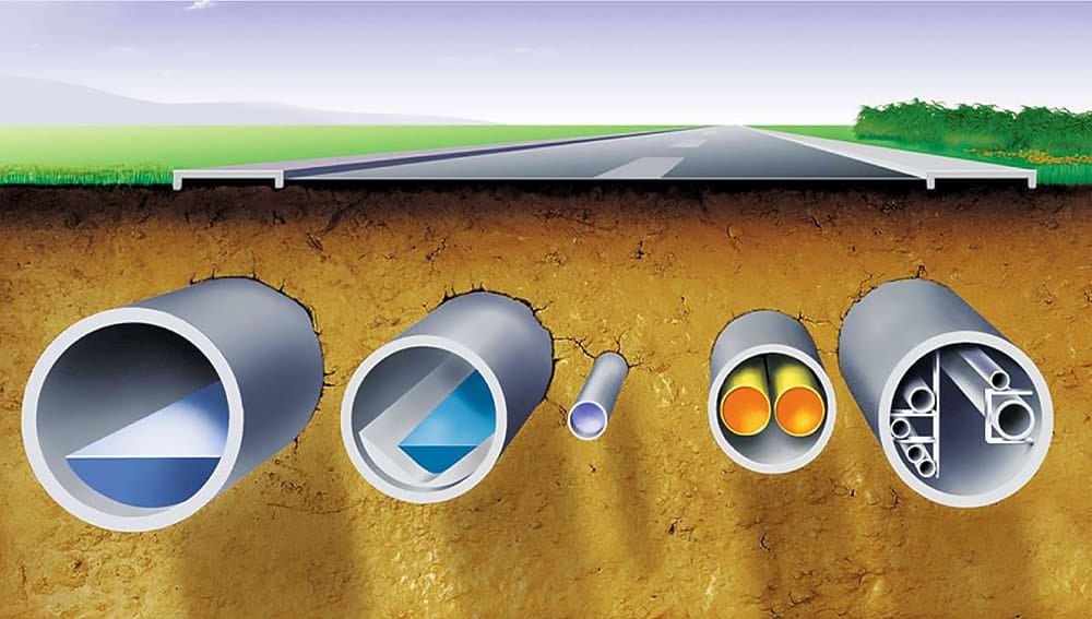
2. Cable Ducts
This laying technique involves installing ducts or pipes in trenches (by horizontal drilling or other ways) and then pulling cables into them (see Figure 2). These ducts or pipes can be made of PVC, concrete, polyethylene (PE), steel, or fiber-reinforced epoxy (FRE), however PVC or PE ducts are most commonly utilized.
The ducts or pipes may be filled with air, bentonite, cement, sand, or water. Typically, each duct has only one cable and is filled with air or bentonite or another material.
Ducts are typically utilized alongside manholes in a system that is popular in metropolitan regions of big cities due to their ease. It provides the option of carrying out civil work separately from electrical work. Furthermore, the flexibility of cable repair or replacement with minimal disruption to local traffic and commercial activity is seen favorably.
In less crowded regions, joint bays would replace manholes to save money.
Laying cables in ducts is regarded as one of the safest types of installation in terms of short circuit protection. It should be emphasized that enough earth cover above the duct bank is required to ensure public safety. It’s also worth noting that manholes can provide a safety risk in the event of a cable or joint explosion.
Empty ducts could be used for a reserve cable if sheath bonding is designed properly. Fiber optic communication cables could be put in the same duct bank.
Figure 2 – Laying cables in ducts

3. Laying in Troughs
The troughs typically comprise precast concrete segments, which are commonly positioned within a trench. Subsequently, the cables are laid within the trough (see Figure 3). The troughs are often filled with sand, and a customary practice is to lay three wires in each trough. The excavated soil is typically utilized as backfill material around the troughs.
The trough can be constructed by either assembling precast sections, each measuring approximately one meter in length, or by continuously pouring concrete to form a single element. The top of the sides can be designed to accommodate a structural cover, such as concrete, steel, or fiber reinforced plastic, which serves to protect the cable that is installed within.
The troughs are typically filled with specialized backfill, such as carefully chosen sand or a weak mix mortar, to facilitate the dissipation of heat. After the trough channel has been constructed, the cables can be installed in a manner similar to an open trench. This can be done either by pulling the wires or by laying them from one junction to another or from a joint to a termination point. Subsequently, covers are positioned.
Figure 3 – Laying cables in troughs

4. Cable Tunnels
Tunnel boring machines are capable of excavating tunnels with a diameter greater than 2-2.5 meters. Tunnels, which have a wide range of applications beyond cable installation, have virtually no technological constraints when it comes to their length. The arrangement of the cables within the tunnel, whether they are placed on steel trays or embedded in the concrete, will be determined by the intended purpose of the tunnel, such as for a metro system or other applications.
Tunnels sometimes coexist with other utilities, such as gas or water. A commonly employed method for installation involves a flexible design where cables are arranged in a trefoil shape (see to Figure 4). Only one out of the four tunnels is equipped with a cooling system. This approach is often used for installing cables with a voltage rating above 170 kV, making it the most preferred method.
A tunnel can be created using the open-cut method, shield method, or pipe jacking method. The pipe jacking method will be discussed in Section #10. The shield method and pipe jacking method share comparable geometries.
The only distinction between them is in their respective construction methods.
1) Open-Cut Method
The open cut method is a technique used for tunnel construction. Initially, commence the process of excavation from the ground surface, followed by the construction of the tunnel in the designated place. Finally, restore the ground surface by utilizing backfill materials. The predominant approach is typically the full face procedure.
2) Shield Method
If the Open-cut method is not feasible, the Shield method should be employed. It can be used in situations where there is considerable road traffic or when the tunnel needs to be built at a great depth, making it difficult to excavate from the ground surface. This is done to avoid interfering with other underground infrastructure such as telephone wires, gas pipes, water pipes, sewage pipes, and subways.
Cables in tunnels can be installed either in a rigid arrangement, which is typically used when there is limited area, or more commonly in a flexible configuration. In the second scenario, both vertical and horizontal snaking are employed, depending on practical factors.
Alternatively, one can also choose to use empty troughs with a horizontal snaking.
Figure 4 – Laying cables in tunnel

5. Microtunneling
Microtunnels are utilized as an installation method in situations where it is not feasible to use open ditches, such as when crossing barriers like railways, rivers, duct banks, and freeways.
This method involves using a thrust-jacking station to push pre-made pipe sections with the same diameter as the final pipe through the earth from a pit. Please refer to Figure 5 for a visual representation. Tunnel boring is exclusively mechanized, employing a remote-controlled microtunnel boring equipment positioned at the forefront of the pipes. This method facilitates the construction of narrow horizontal tunnels with diameters ranging from 0.3 m to 1.2 m.
The lengths of the sections often do not surpass 150 meters. If the length of the drilling is excessive, it can be divided into two halves using a central work shaft and two lateral exit shafts.
Microtunnels are used in situations where open trenches are not practicable. Such trenchless drilling technology necessitates extensive geological knowledge of the terrain. Before specifying the civil work to be done, a geological investigation and a complete survey of the subsoil character are required, including the location (or lack thereof) of the ground water table.
Figure 5 – Microtunnelling

After the microtunnel and cable installation are completed, no maintenance is necessary. Because the tunnel tubes provide great mechanical protection, damage from the outside is extremely improbable, eliminating the need for mechanical repairs. If the cable fails inside, it can be readily removed out of the duct and replaced.
Due to the ducts’ limited width, cable joints cannot be used to repair the tunnel portion.
6. Cable Shafts
Cable shafts are circular or rectangular excavations constructed vertically or at an angle of less than 30 degrees to the vertical. Such shafts are dug, for example, at the start and end stations of a microtunnel. The cables in these shafts are normally mounted on a steel structure, and the length of the shaft determines the kind of system (rigid or flexible).
The most typical installation procedures involve a flexible design with cables placed in a trefoil formation.
Shafts are commonly employed in hydraulic generation plants where the power generated by underground equipment must be carried up to the start of the aerial lines. Shafts may also be seen on cable routes in cities when cables must be routed via deep tunnels and connected to overhead lines or substations.
Cables can be clamped to the shaft walls or metal constructions.
The shafts are sometimes employed as the production plant’s vents, and the air temperature during typical operating circumstances must be addressed while building the installation architecture.
Figure 6 – Shaft in front of a cable microtunnel

Shafts are frequently constructed as part of power plant or tunnel constructions, and the cable installation design must take into account the existing infrastructure. Sometimes calculations must be performed to ensure that the current facilities can support the weight of the cable and the required structures.
In the case of Foundation Fieldbus (FF) cables, junction chambers must be installed on purpose along the shaft to comply with the maximum cable length. The dimensions of the chambers must take into account the size of the joints, the number of cables, and the structures to be erected.
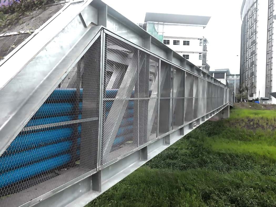
7. Bridges
This strategy allows for the avoidance of costly and often technically complex methods when crossing specific or delicate areas. The cables are placed either within or outside the bridge, depending on the bridge’s structural design. The most typical installation procedures involve a flexible design with cables placed in a trefoil formation.
Existing bridges are commonly used where the cable route crosses rivers, trains, traffic intersections, and so on. Some bridges have a natural space to allow cable placement, either inside the bridge or on the sidewalk. On concrete bridges, the cables are installed in prefabricated troughs in the sidewalk, where they are directly laid.
The cables can alternatively be directly cleated on the bridge or routed through ducts. Before selecting to use an existing bridge as a crossing, significant consideration should be given. The designer must address the dynamic mechanical stress induced by vibrations, elongation, and bending at connections, as well as environmental stress factors such as sunlight, heat, and wind pressure.
When building new bridges, always include a room for potential future cables. Cast-in ducts make it simple to route the cables across the bridge. However, the offset of the cables at the piers is quite critical.
Figure 7 – Bridge for high voltage cables
8. Mechanical Laying
This approach, derived from the standard trench technique, is appropriate for underground cables and consists of opening the excavation while concurrently laying the three phases, as well as possible earthing and telecommunication cable, and backfilling.
When paired with the usage of weak-mix mortar, it provides the following:
- Good cable protection from external harm.
- Good control of the cable’s direct thermal environment.
- Good environmental protection in the event of a short-circuit.
- Trench size is reduced when compared to conventional techniques, and
- Reduced work duration
There are three options for arranging the mechanical laying site:
Option #1 – Mechanically excavated narrow trench, and separate laying of the cables: laying and backfilling is done by traditional methods after the trench has been mechanically excavated;
Option #2 – Trench excavation and cable laying both mechanical: trench excavation, cable laying and sometimes the backfilling are performed by a machine.
Option #3 – Trench excavation, cable laying, backfilling all continuous and mechanized: with this method, trench excavation, cable laying and sometimes trench backfilling can all be done simultaneously in a continuous process over the full length of a homogeneous portion of the link (the joints have to be prepared beforehand). This technique is only used for voltages under 170 kV.
Cables are often buried straight in trefoil shape, with a minimum cover of one meter.
Figure 8 – Mechanical laying of high-voltage cables

This method necessitates the use of specialized equipment, which is costly and heavy. The transportation of equipment from one location to another must be properly planned (cost, duration).
9. Horizontal Drilling
This method is directly evolved from directional drilling techniques used in the oil sector and is utilized for crossing major barriers (e.g., rivers, railway tracks, freeways, etc.) as well as longitudinal drilling. The procedure contains three phases: Drilling of the pilot hole, backreaming (practice of pumping and rotating the drillstring while simultaneously pulling out of the hole), and placement of the final pipe(s). Drilling mud (usually bentonite) washes cuttings to the surface, lowers friction, stabilizes the borehole, and cools the drill head.
In general, the mud is filtered and recovered for reuse in a closed circuit. The type of the soil is critical when contemplating this strategy. The cables are pulled into the pipes once they have been placed. Three PE ducts are typically pulled in a single drill using one cable per duct.
These are either air or bentonite-filled.
Drilling can begin on the job by entering a pre-dug launching pit or by starting from the road or soil surface, often known as surface launch.
Watch Video – How to Install Cables Under the Road Using Horizontal Drilling
10. Pipe Jacking
The first section of pipe may have a steel cutting curb that attacks the soil in place while also protecting the persons excavating the soil. Pipe jacking can be done for pipe diameters ranging from 0.4 m to 3.2 m. This technique is useful for lengths greater than 100 m, and pipe jacking work can be done across distances of 500 or 600 meters.
Pipes are often made of either concrete or steel. The cables are installed as tunnels or microtunnels, depending on their diameter. If necessary, the ducts and the space between the ducts and the pipe can be filled.
Pipe jacking is an environmentally friendly installation technique because it has no negative effects on the surrounding environment. The excess dirt (equivalent to the pipe volume) is evacuated from the ground, meaning that displacement of in situ and settled soil can be avoided. Pipe jacking is not appropriate in hard soils such as limestone, sandy shale, or granite. Pipe jacking is not suggested in heterogeneous soil with blocks (clay, flint, and sandstone).
Before deciding on the pipe jacking method, the soil’s type and composition must be researched. Without this study, pipe jacking could be delayed owing to a block, requiring a manual and time-consuming procedure at the front of the first pipe when the block is chopped into pieces. This action is not possible with pipe sizes smaller than 800 mm.
Only excavation from the surface, or the use of explosives within the pipe (if possible), can prevent the installation from being abandoned. In such a circumstance, a fresh pipe jacking operation must begin at a different depth or position. Cathodic protection must be considered if pipe jacking is performed with steel pipes.
Figure 9 – Pipe jacking for HV cables
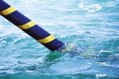
11. Embedding
The embedding technique involves dredging the river bed from a barge or amphibious vehicle and embedding the pipes or wires themselves (see Figure 10). When crossing navigable waterways, this method requires that river traffic be stopped or diverted during excavation and laying operations.
Due to recent technological advancements in the field of embedding machines and other ancillary equipment (remote operated vehicles (ROV), etc.), cable burial is now possible, with various ways, up to a significant depth and almost in any type of riverbed. To minimize costs, embedment should be limited to areas where the danger of cable breakage outweighs the expense.
Of course, the cost of a repair, assessed against its likelihood, must be compared to the cost of protection. The outcome of this strategy may differ depending on the circumstances, such as in a short link with substantial human activity (shipping and anchoring).
A comprehensive embedding may be better, although in a lengthy connection with low local activity, an exposed cable (save for restricted areas with specific protection) may be far more cost effective, even after accounting for the cost of a possible repair.
Figure 10 – Embedding pipes or cables in the river bed

12. Use of Existing Structures
Occasionally, the decision may be made to utilize preexisting or old constructions such as racks or trays, as well as abandoned utility ducts like those used for water, gas, or pipelines, to house the cables. Therefore, it is imperative to conduct a comprehensive examination of these structures and thoroughly clean them, particularly when it comes to ducts.
Discovering alternative configurations for high voltage power lines is increasingly challenging, particularly in urban or protected regions. Utilizing preexisting structures is highly appealing for resolving integration issues in the landscape and has the potential to significantly decrease expenses and initial delays.
Good Tool (XLSX) – Cables Database tool for design of cables connections, laying and terminations
Cables Database tool for design of cables connections, laying and terminations
13. BONUS: Power Systems Book For Students and Practicing Engineers (PDF)
Download Power Systems Book For Students and Practicing Engineers (PDF, 8.7 MB) (for premium members only):
References:
- Integration of a new HV underground cable system in the network by Cigre
Related electrical guides & articles


Edvard Csanyi
Hi, I'm an electrical engineer, programmer and founder of EEP - Electrical Engineering Portal. I worked twelve years at Schneider Electric in the position of technical support for low- and medium-voltage projects and the design of busbar trunking systems.I'm highly specialized in the design of LV/MV switchgear and low-voltage, high-power busbar trunking (<6300A) in substations, commercial buildings and industry facilities. I'm also a professional in AutoCAD programming.
Profile: Edvard Csanyi

Dear Sir, Do you have any article or literature on how to design concrete cable tunnels or trenches to support effective cooling of the high-voltage cables and as well as provide access for maintenance and inspection