
CTs and Their Secondary Circuits
Welcome to the first part of our three-part series on current transformers (CTs) and their secondary circuits. In this series, we will delve into the intricacies of CT operation, explore the importance of secondary injection testing, examine the concept of “burden” in CTs, and discuss various considerations when choosing between 1 Amp and 5 Amp CTs.
 Comprehensive Guide to Secondary Injection Testing of the Current Transformers (Part 1) - CTs and their Secondary Circuits
Additionally, we will provide practical case studies, analyze the impact of load resistance on CT burden calculations, emphasize the significance of shorting and isolating links, and outline the correct sequence for CT isolation and shorting in electrical systems.
We will also guide you through the optimization of CT loop checks and provide a comprehensive testing procedure for CT shorting and isolating facilities to ensure their effective functionality and reliability.
In this first part, we begin by unraveling the inner workings of current transformers. We will explore the fundamental principles that govern their operation and their crucial role in current measurement and protection. Note that this article is not dedicated to CT theory!
However, understanding how CTs work is essential for comprehending the subsequent topics discussed throughout this series.
Furthermore, we shall dive deeper into the concept of “burden” in current transformers, shedding light on why the CT secondary circuit must never be open circuited. We will discuss the implications of open circuit conditions and the potential risks associated with neglecting this crucial aspect of CT operation.
To provide a comprehensive understanding of CTs, we will then differentiate between CT burden and load in power transformers. This section aims to clarify the distinction between these two terms and highlight their respective roles in CT performance. Additionally, we explore the considerations and applications involved in choosing between 1 Amp and 5 Amp current transformers.
We will examine the factors that influence this decision-making process and discuss the suitability of each type in different scenarios.
To illustrate the calculations involved in determining the VA burden, we present several case studies. Each case study demonstrates the analysis of CT secondary connections with varying load resistances. Through these examples, we highlight the impact of load resistance on CT burden calculations and provide practical insights for engineers and technicians.
Lastly, we discuss the importance of shorting and isolating links in the CT secondary circuit. We emphasize their role in ensuring accurate CT measurements, protecting equipment, and preventing hazardous conditions. We also outline the correct sequence for CT isolation and shorting, underscoring the significance of following the prescribed procedures in electrical systems.
By the end of this series, we aim to equip you with a comprehensive understanding of current transformers and their secondary circuits. Whether you are an electrical engineer, technician, or enthusiast, this series will provide valuable insights into the intricacies of CT operation and help you optimize their performance and reliability.
Now, let’s begin our exploration of current transformers with a detailed explanation of how they actually work.
- How Current Transformer Actually Work
- Introduction to Secondary Injection Testing of CTs: Ensuring Correctness of CT Secondary Wiring
- Exploring the Concept of “Burden” in CTs: Why CT Secondary Must Never Be Open Circuited
- Understanding the Distinction between CT Burden and Load in Power Transformers
- Choosing Between 1 Amp and 5 Amp CTs: Considerations and Applications
- Illustration of VA Burden Calculations:
- Case Study 1: Assessing VA Burden in a Short Circuited CT Secondary
- Case Study 2: Analysis of CT Secondary Connected with 0.5 Ohms Load
- Case Study 3: Analysis of CT Secondary Connected with 1 Ohm Load
- Case Study 4: Analysis of CT Secondary Connected with 0.5 Ohm Load
- Case Study 5: Analysis of CT Secondary Connected with 1 Ohm Load
- Impact of Load Resistance on CT Burden Calculations: Analysis with Ideal Transformer and CT Loop
- CT Secondary Circuit: Importance of Shorting and Isolating Links
- Importance of Following the Correct Sequence for CT Isolation and Shorting in Electrical Systems
- Optimizing CT Loop Check: Schematics Examination, Sliding Link Positions, and Isolating Link Wiring
- Testing Procedure for CT Shorting and Isolating Facilities: Ensuring Effective Functionality and Reliability
1. How Current Transformer Actually Works
As always, with the respect to engineers beginners and refreshers, we must start with the some basic theory. The operation of a current transformer (CT) is based on the fundamental principle of electromagnetic induction. When alternating current flows through the primary winding of the CT, the primary current generates a magnetic field, denoted as H = N×I, within the core of the CT. This magnetic field gives rise to a magnetic flux within the core.
The magnetic flux is then coupled to the secondary winding of the CT, which is wound around the core.
The secondary winding of the CT is connected to a burden, which can be a measuring instrument or a protective relay. Once the secondary CT is connected to the burden, alternating current begins to flow through the secondary winding of the transformer.
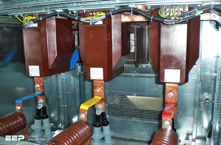
Figure 1 – Block type medium voltage current transformers
The current flowing through the secondary winding creates a magnetic flux that opposes the main flux generated by the primary winding. This opposing flux in the secondary winding balances the primary flux, resulting in a net flux within the core equal to the difference between the primary and secondary fluxes.
It is important to note that as long as the secondary winding remains connected to the burden, the flux in the core remains within the rated flux capacity of the core. This ensures that the CT operates within its designed parameters and provides accurate current measurement or reliable protection to the connected circuit or equipment.
Suggested video – How a CT works
2. Secondary Injection Testing of CTs
Ensuring Correctness of CT Secondary Wiring
The secondary injection test is a vital procedure conducted on current transformers (CTs) to ensure their proper functioning and reliability. This test allows us to verify several critical aspects of the CT, including the integrity of the CT secondary wiring, phase segregations, connection of the actual VA burden, insulation of the secondary circuit, single point earthing, and relay CT ratio settings.
Three-phase secondary injection test kit is shown in Figure 2 below.
During the secondary injection test, a known current is injected into the secondary winding of the CT, simulating the primary current. By carefully monitoring the response of the CT and comparing it to the expected values, we can assess the performance and accuracy of the CT.
Phase segregations are another crucial aspect evaluated during the secondary injection test. By examining the phase relationships of the currents measured in the CT secondary, we can confirm that the CT secondary wiring is not interchanged. Furthermore, the test allows us to verify the actual VA burden connected to the CT.
This is essential in ensuring that the CT can handle the load and accurately deliver the required measurements to the connected instruments or protective relays.
Figure 2 – Three-phase secondary injection test kit

The secondary injection test also evaluates the insulation of the secondary circuit. It ensures that the insulation materials and connections are intact, preventing any leakage or short-circuits that could compromise the CT’s performance. In addition, the test verifies the effectiveness of single point earthing, which is crucial for safety and fault detection.
It confirms that the CT’s earthing connection is reliable and that any fault currents are effectively detected.
Lastly, the secondary injection test serves as a prerequisite for the primary injection test. Before conducting the primary injection test, which involves injecting current directly into the primary winding, it is essential to verify the accuracy and reliability of the CT wiring through the secondary injection test.
In summary, the secondary injection test is a critical step in validating the functionality and integrity of current transformers.
By assessing various parameters such as CT secondary wiring, phase segregations, burden connection, insulation, earthing, and relay CT ratio settings, this test ensures the CT’s secondary wiring accuracy and reliability, providing confidence in its performance for accurate measurement and protection in electrical systems.
Good Reading – Switchgear control circuits: trip, BCPU and alarm, indication, and interlock
Mastering switchgear control circuits: trip, BCPU and alarm, indication, and interlock circuits
Go back to the Contents Table ↑
3. Exploring the Concept of “Burden” in CTs
Why CT Secondary Must never be open circuited?
The load placed on a current transformer (CT) is commonly referred to as a “burden“, a term that holds significant importance in understanding the operational requirements of CTs. To comprehend why the load on a CT is termed a burden, we must delve into the fundamental principles governing CT operation.
Similar to a conventional transformer, the primary purpose of a CT is to step down high currents to lower, measurable values for accurate monitoring and protection purposes. In the CT secondary circuit, the current is transformed to a reduced magnitude in proportion to the turns ratio of the transformer.
Related electrical guides & articles


Muhammad Kashif
Muhammad Kashif Shamshad is an Electrical Engineer and has more than 17 years of experience in operation & maintenance, erection, testing project management, consultancy, supervision, and commissioning of Power Plant, GIS, and AIS high voltage substations ranging up to 500 kV HVAC & ±660kV HVDC more than ten years experience is with Siemens Saudi Arabia.Profile: Muhammad Kashif
