
Why Doing Insulation Testing?
The objective of this technical article is to provide certain criteria and time intervals for conducting insulation tests on electric motors, generators and other electrical equipment. Testing is done to ensure that the equipment is intact and to provide a level of confidence that the insulation will continue to function reliably until the next significant power outage.
 Insulation tests on electric motors and generators: DC High Potential Testing (HiPot)
Even if some of the overvoltage test currents are lower than the generally regarded lethal values, the energy that is stored as charge in the insulating capacitance can be fatal. Before the device may be said to be dead-dead, the charge that it has stored must first be discharged, also called “drained.”
Between the thing being tested and the ground in the surrounding area, there is a dielectric capacitance that stores the charge.
The purpose of this technical article is not to serve as a comprehensive technique for testing insulation, and it is expected that individuals performing the tests will be conversant with safety as well as other specific aspects of high-voltage insulation testing.
- Testing Integrity of 460V and Higher-Voltage AC Devices
- DC High Potential Testing (HiPot)
- Generator Rotor Winding Overvoltage Testing
- Generator-Neutral Buses or Cables
- Testing Cables (5 kV and Higher)
1. Testing integrity of 460V and higher-voltage AC devices
Periodically conducting an insulation megger test at either 500V or 1000V DC is recommended in order to ascertain whether or not equipment operating at 460V or higher voltages is reliable. It is recommended that the frequency of testing be based on the site-specific environmental conditions as well as the expertise gained with the specific piece of equipment.
In most cases, the time that passes between tests should not be allowed to exceed three years.
Before applying power to the electrical devices, you need to ensure that it satisfies the following minimum megohm requirement, which is based on the conditions of operation and applies to all AC electrical devices with 460 V or greater in voltage. The following criterion for the test implies that the apparatus being evaluated is kept at a temperature of 25 degrees Celsius.
The results of measurements taken with this method at temperatures higher than 25 degrees Celsius are expected to be conservative.
The correction factors vary depending on the specific class or kind of insulation. In general, an increase in temperature leads to a decrease in insulating resistance due to the greater availability of free electrons for conduction.
The minimum megohms can be estimated to be approximately three times higher at a temperature of 25°C, which is commonly used as the ambient testing temperature. Alternatively, for a three-phase test, the minimum megohms can be calculated as three megohms per kilovolt.
It is customary to conduct ground testing on motors without disrupting the internal phase connections, as seen in Figure 1.
Figure 1 – Motor insulation resistance (minimum megohms)

The above motor calculation is often used for other devices in an industrial setting.
In the name of simplicity, it is anticipated that the insulation resistance for a single-phase test would be three times greater, equivalent to 9 megohms per kilovolt. This estimation is considered conservative, as it accounts for the presence of phase-to-phase insulation resistance that diminishes the actual factor, particularly when untested phases are grounded.
In the case that multiple equipment are being tested concurrently, it may be necessary to separate or isolate individual equipment units to ensure compliance with the minimum standards.
The routine insulation testing of electrical equipment units, including buses, cables, circuit breakers, generators, and transformers, is commonly conducted in the industry using the motor standard, despite the fact that each type of unit has its own specific minimum megohms requirement.
Consideration should be given to using a 500V test during routine or short outages to reduce the possibilities of extending the outage for cleaning and dryout, and a 1000V test should be reserved for overhauls and longer outages where a higher-proof test for an undefined future life is desired. Here, 1000 V is essentially an overvoltage- or hipot-test for low-voltage equipment (480V devices).
The common practice in the field is to use 1 megaohm for every kilovolt, which gets rid of the plus 1 kV, and it does not account for variances in temperature. This is particularly concerting. When electrical equipment was energized at a resistance of 1 megohm per kilovolt, numerous reports indicated that it either failed or exploded.
Note that IEEE Standard 43, Testing Insulation Resistance of Rotating Machinery, says that the needed megohms should be increased by 2 when megger-testing one phase at a time (with the other two phases grounded), unless guards are used, in which case the readings should be multiplied by 3, and that this should be done when testing one phase at a time with a megger.
Suggested Video – “Megger” insulation test on a bad motor
The recommendation selected a more straightforward and cautious method of multiplication by a factor of 3 in both instances, resulting in a value of 9 megohms per kilovolt at normal temperatures. This criterion is likewise applicable to an entire system or its constituent components at the level of the apparatus. Put simply, it is permissible to separate the electrical devices in order to assess their compliance individually.
For instance, the motor can be disconnected from the cables, and if both the cables and motor satisfy the requirement on their own, they can be rejoined and powered.
Because the voltage being measured is direct current (DC), the capacitive charging current will decrease as the period of the test goes on, which will result in greater megohm results.
A PI value of 2 is generally considered to be acceptable in most situations; however, this is not the case if the equipment has a history of having lower PI values.
Good Reading – Never let an electric motor drop dead. Learn how to listen and read the motor’s soul.
Never let an electric motor drop dead. Learn how to listen and read the motor’s soul.
Go back to the Contents Table ↑
2. DC High Potential Testing (HiPot)
During major turbine overhaul outages (HP turbine for cross-compound units), generators and motors with voltages of 2 kV and above should be routinely overvoltaged tested. Cables that feed motors are typically included in the overvoltage test for convenience (motor routine values are not regarded high enough to unduly stress cable insulation).
Otherwise, routine overvoltage testing of wires is not normally advised.
It is impossible to predict whether the equipment insulation will fail during overvoltage (hipot) testing prior to testing. As a result, while scheduling the test, allow for time to get materials and repair or replace equipment. However, the routine test values provided in this technical article for motors and generators are the minimum values (125% instead of 150% maximum) specified by IEEE.
Before conducting a hipot test on generator and motor stator windings, it is typically necessary to do a polarization test using a 1000V megger with a polarization index (PI) of 2 or higher. The polarization test, also known as the PI test, refers to the ratio between the insulation resistance values taken at 10 minutes and 1 minute.
This ratio serves as an indicator of the suitability of the winding for the overvoltage test.
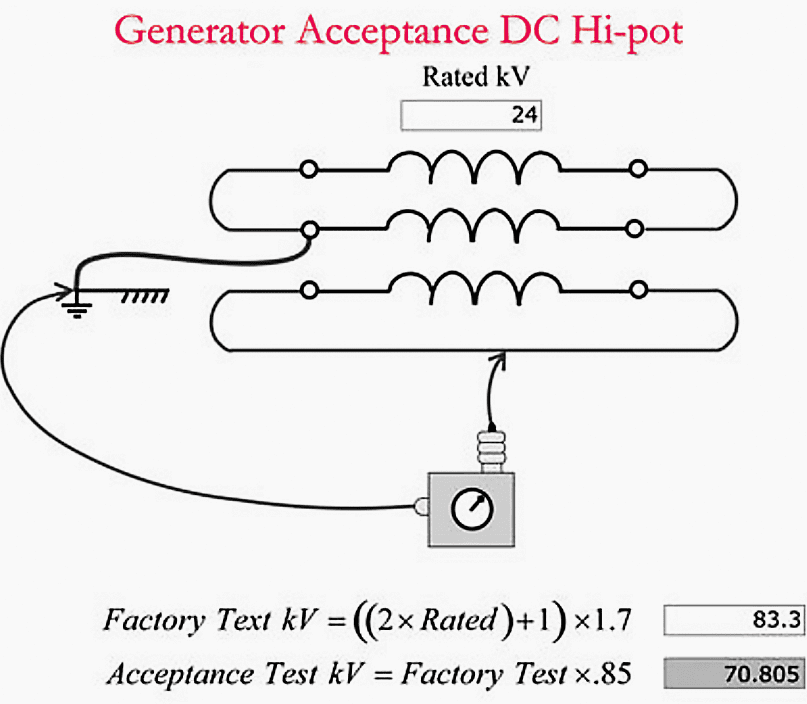
Figure 2 – Generator DC hipot acceptance test
A low PI (less than 2) may indicate that cleaning, dryout, or repair is required before the hipot can be performed.
Nevertheless, it is worth noting that certain insulation systems that are in a satisfactory state may not provide a Polarization Index (PI) value of 2 or higher. In situations when this condition is met, and the polarization index (PI) measurement aligns with past measurements conducted on the specific insulating system, it is permissible to proceed with the overvoltage testing.
When conducting insulation resistance tests, it is necessary to ensure a minimum insulation resistance using a 1000V megger. For isolating one phase from the other phases, as desired for generators and cables, a minimum insulation resistance of 9 megohms per rated kilovolt is required.
On the other hand, when testing all three phases simultaneously, as is done for motors, a minimum insulation resistance of 3 megohms per rated kilovolt is necessary.
Important Note!
The task of conducting overvoltage testing should be exclusively entrusted to technicians or engineers who possess a comprehensive understanding of the necessary safety protocols and testing processes, and have received appropriate training to carry out such testing.
In order to mitigate the financial implications associated with test failures, it is recommended that the overvoltage testing of generators with a capacity of 10-MVA and above be conducted under the supervision of experienced supervisors or engineers who possess relevant expertise in overvoltage testing.
Figure 3 – Generator routine test

Note that most generator manufacturers recommend 125-150% of rated kV for suitability for continued service tests.
Motors and generators are often tested at the starting of an outage to provide time for any necessary repairs to be completed within the outage timeframe. Furthermore, the testing should be done while the apparatus is dry (before disassembly or in a cool standby condition).
Normally, generators are tested fully assembled and under hydrogen pressure (where applicable). Before performing overvoltage testing on generators with inner water-cooled stator coils, the water is generally drained by pulling a vacuum to allow megger testing for an acceptable PI and minimum insulation resistance values.
Wye-connected generators are generally disconnected at the output and neutral ends, as seen in Figures 2 and 3 above. To eliminate transient voltages if the test is abruptly interrupted, each end of the winding is connected with copper bonding wire, and each phase is individually tested to ground, with the other two phases grounded.
Figure 4 – Motor DC acceptance test

Typically, all three phases of motors lacking neutral leads, which are brought up to the termination box, are tested concurrently with respect to ground. In typical practice, motors and their corresponding cables are commonly subjected to joint testing, wherein all three phases are interconnected and linked together. This testing arrangement is illustrated in Figures 4 and 5.
The separation of cables from the motor should only be considered when the readings obtained from the combined motor-cable system are deemed unsatisfactory.
In such cases, it is recommended to terminate the test by gradually dropping the voltage to zero.
The successful completion of a test is determined by achieving of the recommended voltage value and the maintenance of a stable current for a duration of one minute. Upon completion of the experiment, it is imperative to gradually decrease the voltage to zero in order to prevent abrupt fluctuations and the emergence of potentially harmful transient voltages.
Figure 5 – Motor DC routine test

Go back to the Contents Table ↑
3. Generator Rotor Winding Overvoltage Testing
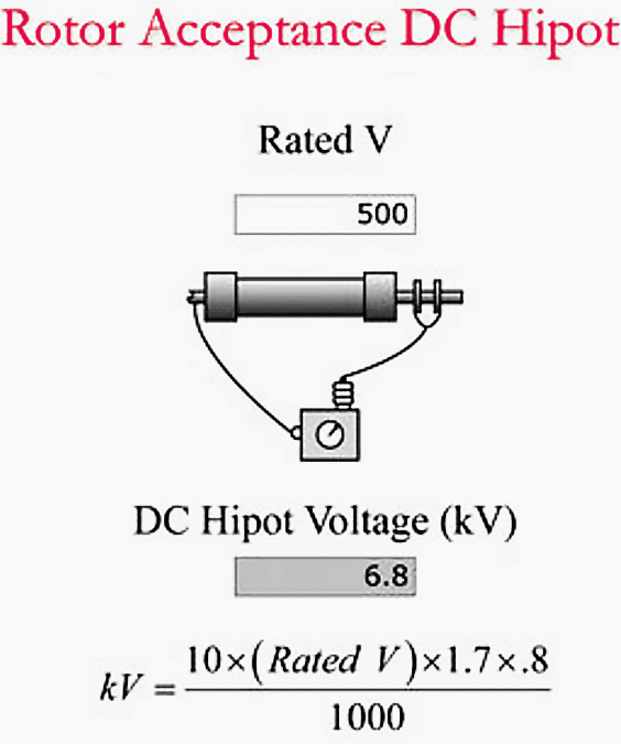
Insulation systems for cylindrical rotor field windings of large generators are typically subjected to DC overvoltage or hot-pot testing at acceptance values subsequent to shipment to the site or after onsite rewinds. In such cases, an external party assumes the cost of repair in the event of a malfunction and must also certify that the apparatus is fit for service.
An illustration of the test and the recommended DC hipot test values can be found in Figure 6. In the event that the test is abruptly interrupted, the majority of manufacturers advise testing at 80% of the factory test value with both ends of the winding shorted together to reduce transient voltages.
Acceptance testing for a 500V field winding would occur at 6.8 kV DC, as illustrated in the figure.
Figure 6 – Generator rotor acceptance DC overvoltage testing
Typically, insulation systems for cylindrical rotor field windings of large generators are subjected to DC overvoltage or hipot testing during the warranty period following one year of use. In such cases, an external party assumes the financial burden of repair expenses in the event of a failure and must also certify that the equipment remains fit for continued operation.
An illustration of the test and the recommended DC hipot test values can be found in Figure 7. In the event that the test is abruptly interrupted, the majority of manufacturers advise testing at 60% of the factory test value with both ends of the winding shorted together to reduce transient voltages.
After one year of operation, a 500V field winding would be evaluated at 5.1 kV DC, as illustrated in the figure below.
Figure 7 – Generator rotor first-year warranty DC overvoltage testing

Field windings on cylindrical rotor generators should be tested routinely during unit overhauls. A PI of 2.0 (measure of moisture or contamination) is typically necessary and is determined by dividing the megohm reading from ten minutes by the measurement from one minute.
The exposed insulation for the collector or slip rings on brush machines frequently accumulates a substantial amount of oil/carbon from the bearings and brushes; therefore, it may be necessary to perform a thorough cleansing of that region in order to achieve a satisfactory PI.
The test procedure is illustrated in Figure 8, which recommends the utilization of an insulation test instrument or a 1000V megger. As illustrated in the figure, the minimum megohm value is 50, which surpasses the standard nonoverhaul requirement of 4.5 megohms for a 500V field or 9 megohms per kilovolt.
This can be accomplished using a test instrument or a 500V meter.
Figure 8 – Generator rotor routine overhaul insulation testing

Go back to the Contents Table ↑
4. Generator-Neutral Buses or Cables
During generator stator overhauls, the generator-neutral bus and/or cable to the grounding transformer should be disconnected at both ends and DC high-pot-tested at the generator stator’s routine value.
Go back to the Contents Table ↑
5. Testing Cables (5 kV and Higher)
Cables with voltage ratings of 5 kV and above should not be subjected to routine cable hipot testing during overhauls, unless there are doubts regarding the cable’s integrity. In order to conduct a comprehensive and regular hipot test, it is necessary to disconnect the cables at both ends due to the elevated test voltages involved and the constraints imposed by the switchgear and related current transformers (CTs).
In order to ascertain warranty accountability and verify the absence of damage during transportation or installation, it is recommended that newly acquired cables undergo hipot- or partly discharge-testing both before to and subsequent to their installation.
The determination of hipot values for cable testing is contingent upon several factors, including the specific type of insulation material utilized, the thickness of the insulation layer, and the voltage class associated with the cable. The number of variables is too extensive to address comprehensively within the scope of this article.
Typically, the post-installation test is conducted at 80% of the factory test value, whereas routine tests are carried out at 60% of the factory value.
The application of high voltage during cable hipot testing has the potential to reduce the lifespan of certain cable insulation systems due to the induction of molecular alterations, voids, or a combination of both inside the insulation material.
It is noteworthy to mention that the levels of motor hipot are considerably lower in comparison to cable hipot values. As a result, they are deemed to be safe for all cable insulation systems.
Recommended Reading – MV distribution system design based on metal-clad drawout switchgear
MV distribution system design based on metal-clad drawout switchgear
Go back to the Contents Table ↑
Sources:
- Electrical Calculations and Guidelines for Generating Stations and Industrial Plants by Thomas E. Baker
- Experience with Stator Insulation Testing & Turn/Phase Insulation Failures in the Power Generation Industry by Heedong Kim, Taesik Kong (Korea Electric Power Company) and Sang Bin Lee Korea University, Seoul, Korea
Related electrical guides & articles


Edvard Csanyi
Hi, I'm an electrical engineer, programmer and founder of EEP - Electrical Engineering Portal. I worked twelve years at Schneider Electric in the position of technical support for low- and medium-voltage projects and the design of busbar trunking systems.I'm highly specialized in the design of LV/MV switchgear and low-voltage, high-power busbar trunking (<6300A) in substations, commercial buildings and industry facilities. I'm also a professional in AutoCAD programming.
Profile: Edvard Csanyi

Best website for all engineers