
Pole Discrepancy Schematics
This article delves into the realm of pole discrepancy in high voltage circuit breakers, shedding light on its mechanisms, applications, and the pivotal role it plays in enhancing system reliability. From understanding the choice between gang (three-pole) and independent (single-pole) operated circuit breakers to dissecting the challenges posed by conventional technologies, we embark on a journey to explore the intricacies of pole discrepancy and its implications in various network topologies.
 Intricacies of a circuit breaker pole discrepancy and its implications in substation operation
Beginning with an exploration of pole discrepancy schematics and the underlying circuitry, we delve into the two-step pole-discrepancy protection mechanism and its applications in different operational scenarios.
Through detailed analyses of pole discrepancy statuses during circuit breaker operations and failures, we aim to unravel the complexities associated with maintaining system integrity in the face of adversity.
Furthermore, we examine the operation of pole discrepancy in one and a half breaker schemes and double bus single breaker schemes, dissecting real-world scenarios and showcasing the practical applications of pole discrepancy schemes in ensuring uninterrupted power supply and mitigating potential network disruptions.
- Understanding Pole Discrepancy in High Voltage Circuit Breakers: Single Pole vs. Three Pole Operation
- Pole Discrepancy Function:
- Two-Step Pole-Discrepancy Protection
- Understanding the Pole Discrepancy Basic Circuit
- Status of Pole Discrepancy When the Circuit Breaker is in Open position
- Status of Pole Discrepancy When the Circuit Breaker is in Closed Position
- Pole Discrepancy Status During Closing When One Pole of the CB is Stuck
- Pole Discrepancy Status During Closing When Two Poles of the CB are Stuck
- Pole Discrepancy Status During Opening When One Pole of the CB is Stuck
- Comprehending Pole Discrepancy Operations Across Various Network Topologies:
- Operation of Pole Discrepancy in Double-Bus Single-Breaker Scheme:
- [BONUS!] – Download Book (PDF) – Engineering Analysis and Applications of High Voltage Engineering
1. Understanding Pole Discrepancy in High Voltage Circuit Breakers
Single-Pole vs. Three-Pole Operation
High voltage and extra high voltage circuit breakers are categorized into two types: single-pole operation and three-pole operation. In single pole operation, each pole of the circuit breaker possesses its own independent mechanism, allowing it to operate autonomously from the other poles or phases. Typically, the phases are denoted as red, yellow, and blue, or alternatively as L1, L2, and L3, although other naming conventions may also be utilized within the network.
Conversely, in three-pole circuit breakers, all three poles are linked to a common shaft, and a single operating mechanism drives all the poles simultaneously. These breakers, also known as gang, operated breakers, ensure that all three poles are always operated together through a single operating rod, eliminating the possibility of any single pole remaining open.
The consequence of a pole discrepancy is the flow of unbalanced current into the ground, leading to system instability. If one or two poles exhibit discrepancies, asymmetrical currents flow through the network, further exacerbating system instability and potentially causing cascading failures. Therefore, it is imperative to rectify these conditions swiftly to restore system balance.
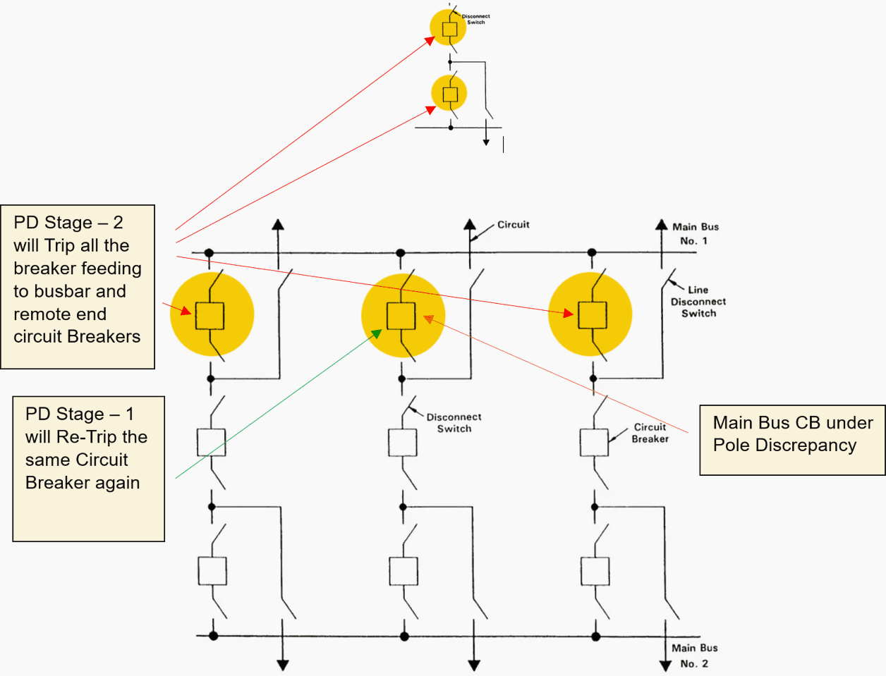
To manage pole discrepancies, a scheme similar to a breaker failure scheme is employed. Upon detection of a pole discrepancy, the pole discrepancy relay initiates a trip command to the affected circuit breaker in stage 1. If the discrepancy persists, the relay proceeds to stage 2, issuing trip commands to all breakers capable of supplying unsymmetrical current through the fault breaker.
Pole discrepancy schemes are commonly implemented at voltage levels of 220 kV and 500 kV, where single pole breakers are typically utilized. These schemes are crucial for maintaining the stability and reliability of high voltage electrical systems, ensuring rapid response to discrepancies to prevent widespread disruptions.
Figure 0 – Operation of Pole Discrepancy in One-and-Half-Breaker Scheme (discussed later in detail)
2. Pole Discrepancy Function
Pole-Discrepancy Protection (PD) is a critical safeguard mechanism employed for three single-pole operating type Circuit Breakers (CBs). This protection scheme relies on auxiliary contacts within the CB’s different phases to detect any discrepancies between the closing and opening operations of the breaker.
Figure 1 – The lockout relay employed in conjunction with the pole discrepancy relay

2.1 Two-Step Pole-Discrepancy Protection
In the event of a pole-discrepancy, the protection mechanism operates in two sequential steps:
Step #1 – The first step initiates a time-delayed trip function for the affected breaker. This delay ensures proper coordination between the poles’ operating times and incorporates an additional safety margin to prevent malfunctions.
Step #2 – The second step introduces a further time delay. If the first-step trip operation is successful, the second-step function is inhibited. However, if the first-step operation fails, adjacent CBs to the faulty breaker are tripped within the station. This step is crucial for preventing widespread disturbances.
Remote CB tripping may also be activated as necessary.
2.2 Understanding the Pole Discrepancy Basic Circuit
Let us first delve into the schematics of the pole discrepancy circuit. Here, we simulate the circuit breaker with a bi-stable relay, which comprises two coils: A1 simulates the circuit breaker closing coil, and B1 simulates the circuit breaker opening coil.
In this setup, we replicate the single-pole operating mechanism. It’s important to note that the single-pole operated mechanism features three closing and three tripping coils. In contrast, the gang-operated circuit breaker mechanism employs a single closing coil for all three phases, as the operating mechanism and shaft are shared.
2.3 Pole Discrepancy Status When the Circuit Breaker is in Open position
Figure 2 depicts the status of the circuit breaker in the open position, indicating that all poles are open. Additionally, the timer labeled PD, known as the pole discrepancy timer relay, is visible. This timer is interconnected with the parallel-connected normally open and closed auxiliary contacts of the circuit breaker. The auxiliary contacts KA, KB, and KC correspond to phases A, B, and C, respectively.
To establish the pole discrepancy circuit, we have interconnected the three normally open contacts of each pole in parallel, along with three parallel-connected normally closed contacts. When the circuit breaker is in the open position, all normally open contacts of each pole remain open, while all normally closed contacts remain closed.
Related electrical guides & articles


Muhammad Kashif
Muhammad Kashif Shamshad is an Electrical Engineer and has more than 17 years of experience in operation & maintenance, erection, testing project management, consultancy, supervision, and commissioning of Power Plant, GIS, and AIS high voltage substations ranging up to 500 kV HVAC & ±660kV HVDC more than ten years experience is with Siemens Saudi Arabia.Profile: Muhammad Kashif
