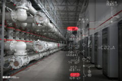
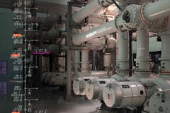
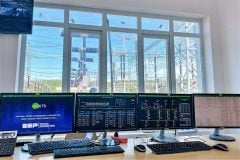
Inspections and tests for GIS
Gas-insulated substations (GIS) are critical components of modern electrical power systems, providing efficient and compact solutions for the transmission and distribution of electricity. These substations utilize sulfur hexafluoride (SF6) gas as an insulating and arc-quenching medium, offering several advantages over traditional air-insulated substations, including enhanced reliability, reduced maintenance requirements, and minimized space requirements.

To ensure the safe and reliable operation of a GIS, it is essential to conduct thorough inspections and tests during the installation and commissioning process. This technical article aims to highlight the key aspects that should be considered when inspecting and testing a gas-insulated substation, as outlined in the provided checklist.
The checklist covers a comprehensive range of inspections and tests, beginning with the physical examination of the substation components. It emphasizes the importance of inspecting enclosures, verifying proper alignment and grounding, and ensuring the quality of paintwork. Additionally, it highlights the significance of installing visible indicators, pressure gauges, and proper materials for gas piping.
It highlights the necessity of fail-safe electrical interlock schemes and the provision of spare contacts and windows for auxiliary relays and alarms/annunciators, respectively.
The checklist also covers various aspects of gas handling, such as the correct operation of gas-handling carts, availability of filling and degassing fittings, and verification of gas pressure and content after filling. It stresses the need for leak testing, calibration of gas pressure gauges, and functionality testing of gas density switches.
Moreover, the checklist addresses important factors related to the overall functionality and labeling of the substation. It emphasizes the correct installation and labeling of front panel devices, operating devices, and phase marking. It also highlights the importance of visual verification of disconnect switches and grounding switch positions, the installation of dispatch numbers, and the marking of gas density gauges in each zone.
Lastly, the checklist includes a set of electrical tests to be performed, such as insulation resistance testing, contact resistance testing, timing tests for circuit breakers, disconnect switches, and earthing switches, as well as functional tests for trip-free and anti-pump circuits.
By following this comprehensive checklist, stakeholders involved in the installation and commissioning of gas-insulated substations can ensure that all critical aspects are thoroughly examined, thereby promoting the safe and reliable operation of the substation throughout its lifecycle.
- Physical Inspection of GIS:
- Installation Verification of GIS:
- Storage of special tools and equipment
- Installation of “ON” and “OFF” indications and SF6 gas pressure gauges
- Maximum allowed induced voltage in GIS enclosure
- Piping materials and fittings for SF6 gas, hydraulic and pneumatic operating mechanism
- Ring core type CTs and proper wiring for CT secondary circuits
- CT secondary circuit wiring within control cabinet and external wiring
- Shorting, isolating, and grounding facilities of secondary terminals
- Safety and Interlocking Mechanisms of GIS:
- Proper wiring materials and specifications
- Proper shielding and grounding of control and instrument cables
- Color coding of control cabinet wiring
- Presence of non-inflammable covers for AC and DC circuit terminals
- Manual operation of disconnect and grounding switches under electrical interlocking release conditions
- Fail-safe electrical interlock schemes
- Mechanical interlocking between disconnect and grounding switch operation
- Spare Contacts and Annunciator Windows:
- Gas Handling and Testing:
- Operation of the gas-handling cart and storage of filling and degassing fittings
- Labeling of lifting devices
- Provision of adequate ladders and walkways for access
- Tightness of all bolted connections
- Filling of each gas section to the rated pressure
- Test SF6 gas for air and moisture content after filling
- Gas leak testing of flanges and joints
- Gas pressure (density) gauges
- Gas density switches and confirm correct set points
- Wiring and Labeling:
- Electrical Tests:
- Conclusion
- BONUS! GIS Drawing and Checklist (PDF)
1. Physical Inspection of GIS
The physical inspection of a gas-insulated substation (GIS) is essential to ensure the integrity and reliability of the equipment. It involves a comprehensive assessment of various aspects, including the following:
1.1 Inspect for Physical Damage or Defects
During this inspection, carefully examine the GIS components for any signs of physical damage or defects. Look for dents, cracks, corrosion, or any other issues that may compromise the functionality and safety of the substation.
Figure 1 – GIS insulation defects: (Left) A void in the insulator; and (Right) Free metal particles on the enclosure


1.2 Check Name Plates and Information
Verify that the name plates on the GIS equipment match the information provided in the drawings and specifications. This ensures accurate identification of components and adherence to design requirements.
1.3 Inspect Enclosures for Alignment and Foundation Fixing
Examine the enclosures of the GIS to ensure they are properly aligned and securely fixed to the foundation. Misalignment can lead to operational issues and potential damage. Verify that the enclosures are in the correct position and firmly anchored.
1.4 Check Quality of Paintwork
Assess the quality of the paintwork applied to the GIS components. Look for any signs of chipping, peeling, or inadequate coverage. Properly applied paint provides protection against corrosion and environmental factors.
Figure 2 – ABB GIS ELK-04 nameplate information


2. Installation Verification
Installation verification is a critical step in ensuring the successful implementation and functionality of a gas-insulated substation (GIS). This phase involves carefully examining the installation process and verifying that all necessary components and systems are properly installed and functioning as intended.
By conducting a thorough installation verification, potential issues can be identified and addressed, ensuring the optimal performance and reliability of the GIS substation. The following topics highlight key aspects of the installation verification process.
2.1 Ensure Proper Storage of Special Tools and Equipment
Verify that all special tools and equipment required for the GIS installation are stored properly. This includes tools specific to the assembly, maintenance, and operation of the substation. Proper storage ensures that these tools are readily available and in good condition when needed.
Figure 3 – Installation of GIS modules


2.2 Verify Installation of “ON” and “OFF” Indications and SF6 Gas Pressure Gauges
Inspect the GIS for the correct installation of “ON” and “OFF” indications, which provide visual cues about the operational status of the substation. Additionally, verify the proper installation of SF6 gas pressure gauges in visible locations, allowing for accurate monitoring of the gas pressure within the system.
2.3 Check the Maximum Allowed Induced Voltage in GIS Enclosure
Examine the GIS enclosure to ensure that the induced voltage within it does not exceed the specified maximum limit (e.g., 65 V). Excessive induced voltage can lead to insulation breakdown and compromise the substation’s safety and performance.
2.4 Inspect Piping Materials and Fittings for SF6 Gas, Hydraulic, and Pneumatic Operating Mechanism
Thoroughly inspect the piping materials and fittings used for SF6 gas, hydraulic, and pneumatic operating mechanisms within the GIS. Verify that the materials meet the specified requirements and that the fittings are securely installed to prevent leaks or malfunctioning.
Figure 4 – SF6 Gas Insulated Switchgear Hydraulic Mechanism (click to zoom)


2.5 Ensure Ring Core Type CTs and Proper Wiring for CT Secondary Circuits
Verify the use of ring core type current transformers (CTs) within the GIS. These CTs provide accurate measurement of current flow. Additionally, inspect the wiring for CT secondary circuits, both within the control cabinet and external wiring, to ensure proper sizing and connection.


