
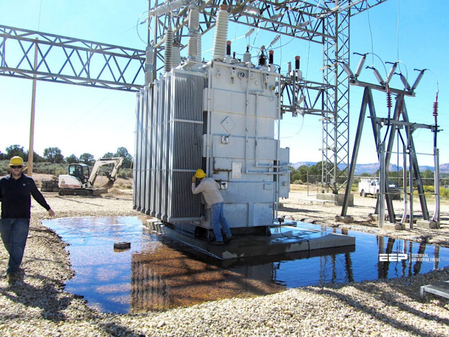
Methods of substation oil containment
Numerous firms in emerging sectors offer conceptual substation oil containment solutions that remain unproven yet have been deployed. This has resulted in several installations of containment systems that are functionally ineffective.

 Best Practice in Substation Oil Containment
There have been and continue to be assertions that once containment systems are installed, they function indefinitely without the necessity for updates or replacements. Regrettably, this is not true. The primary challenge in oil containment is managing precipitation and ensuring complete containment of any oil sheen or significant oil discharge.
Consequently, oil containment resembles the Wild West.
Numerous technologies appear promising yet remain unverified and fail to perform as advertised. Can we ascertain that the oil containment system implemented will be effective in the event of a large-scale leak or fire? In many instances, the response is negative, resulting in the end user being responsible for the cleanup and any penalties related to the discharge.
Various circumstances, including temperature, precipitation, soil saturation, as well as snow and ice, influence the optimal solutions for your substation.
Table of Contents:
- Pool & Pump
- Oil Water Separators
- Oil Float Valves
- Oil Sensing Pumps
- Retention Ponds
- Earthened, Stone Berms or Fiberglass Walls
- Drainage Ball Valves
- Passive System Pump-Filter-Contain
- Passive Oil Containment
- Attachment (PDF) 🔗 Download ‘Design Guide for Uninterruptible Power Supply System’
1. Pool & Pump
The Pool and Pump method for oil containment is highly effective in containing transformer fluids. These pits or pools are often constructed from concrete and accommodate a minimum of 100% of the oil content, in addition to 10% for precipitation. A challenge with pool and pump enclosures is the necessity for regular pumping of rainwater.
Regrettably, some organizations lack the personnel to inspect all contaminants following a precipitation. This results in non-pumping, rendering the capacity of these pits insufficient to allow a complete oil discharge.
This also creates a breeding ground for mosquitoes and algae if not drained.
Figure 1 – Transformer pool and pump for oil containment

2. Oil Water Separators
Various types of Oil Water Separators operate on the fundamental principle that oil is less dense than water. Oil Water Separators must be engineered to handle maximum flow rates and stormwater runoff to guarantee that the flow does not above the calculated design capacity.
The image illustrates that the water flow is decelerated upon entering the Oil Water Separators and is channeled into various chambers equipped with coalescing plates or filters. The primary misperception of the Oil Water Separators is that it requires no maintenance. Nonetheless, in the absence of adequate maintenance and inspections, operational and mechanical failures may result in leaks or inadvertent oil release into water.
Oil/water separator is a stationary wastewater treatment tank, filled with water. It contains specially designed internal baffles and coalescers to accelerate the separation process.
Figure 2 – Substation oil & water separator

3. Oil Float Valves
Various types of oil float valves are utilized in distinct oil containment zones. The benefit derives from getting elevated flow rates through a singular central discharge point. The valves operate based on the idea of specific gravity between oil and water.
If rainwater exits through the valve, it remains open until the specific gravity alters due to an oil spill. In an oil spill, the valve senses the alteration and closes, so halting all flow. These valves necessitate maintenance, which is often neglected. Similar to numerous matters, if it is functioning effectively, do not concern yourself with it.
The difficulty, however, lies in the possibility that a filthy or damaged float may fail to function when needed.
Figure 3 – Oil float valve

4. Oil Sensing Pumps
Numerous oil detection pumping devices function similarly to automatic sump pumps. Oil detecting pumps facilitate the pumping of water through the use of a float mechanism. When the water level reaches a specific height, the pump activates and continues to operate until the float mechanism deactivates it. These systems employ oil detection sensors that identify oil on the water’s surface.
Upon detection of oil, an alert activates, indicating a problem, and the pump ceases operation.
Oil sensor pumps can achieve an optimal flow rate with regular maintenance.
Figure 4 – Transformer oil sensing pump

5. Retention Ponds
Retention Ponds are utilized in regions that possess the necessary space. Most substations lack sufficient space to accommodate a retention pond. Rainwater from the containment area is channeled to the holding ponds, and in the case of an oil spill, the oil is diverted to the pond.
The ponds consistently contain water, causing the oil to move up to the surface. The ponds are designed similarly to a big oil-water separator, featuring a series of weirs and baffles to maintain surface water and facilitate discharge at a singular location.
Potential issues encompass fauna resulting from the establishment of habitats in these ponds, which may also be susceptible to an oil spill.
Figure 5 – Retention pod

6. Earthened, stone Berms or fiberglass walls
Numerous earthen, stone, or fiberglass wall berms exist. These solutions are implemented by compacting the earth, enabling the berm to retain any spilled oil. This system facilitates the gradual drainage of water. In an oil spill, this method is designed to contain the oil. Numerous instances exist where corporations have employed a fabric in the stoned berms designed to facilitate water drainage while retaining oil.
Nevertheless, in numerous instances, these fabric windows become rapidly slashed, permitting less water drainage.
Figure 6 – Earthened, stone berms or fiberglass walls

7. Drainage Ball Valves
Ball valves are utilized in various oil containment basins for the manual drainage of containment zones. When utilized correctly, this technique necessitates sufficient workers allocated to physically inspect the water in each enclosure after a downpour.
If no apparent sheen is present, the valves may be opened.
The principal problem associated with this type of system is the availability of workers required to physically attend the stations to open the valves and, crucially, to remember to close them upon departure.
Figure 7 – Drainage Ball Valve

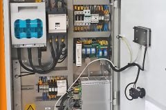
8. Passive System Pump-Filter-Contain
A passive system that circulates water, filters debris, eliminates oil sheen, and contains spills in the event of an oil leak. This is a commonly utilized method for containment zones that involve pools and pumps.
Figure 8 – Passive system Pump-Filter-Contain

9. Passive Oil Containment
Passive oil containment has been effectively utilized for over two decades across many applications in oil containment. These passive items can be integrated with various contemporary technologies to enhance system performance.
Passive filtering employs a combination of polymer and absorption technologies to purify rainwater, with the distinctive capability to eliminate oil sheen, although it becomes entirely ineffective during substantial oil spills.
These passive filters facilitate water filtration and the elimination of oil sheen from a containment area. In the event of a complete oil leak, the oil is absorbed by the medium and undergoes a process known as tackifying, resulting in a comprehensive seal. The total cessation of all water flow occurs within 10 to 30 seconds. A Petro-Pipe or Plug a Pump-Thru-Barrier will maintain water flow and discharge for a duration of up to 1 hour.
No oil is discharged in any of the items.
Figure 9 – Blue Media in Tube allows rainwater to drain 24/7/365

Technology of Blue Media in Tube allows rainwater to drain and seals with and overload of oil preventing any oil from escaping. After Oil has stopped bottom Media is removed a total seal is made NO OIL IS RELEASED.
Numerous passive filters are currently in operation. Concrete basins offer several water drainage alternatives, including the utilization of a passive flanged pipe with a housing integrated into the concrete at a 25° slope, facilitating the insertion of the filter, which can be secured with screws.
This generates hydraulic pressure to facilitate the discharge of water from the containment basin at a rate of up to 3 gallons per minute.
Figure 10 – Passive filters installed

Figure 11 – Corner passive filter close look

The images above depict passive filters fitted in each corner to facilitate uniform water drainage in the basin. The concrete floor is excavated in front of the installed pipes to facilitate the drainage of all water from the basin while ensuring positive head pressure on the filter medium.
The expected functional life of the filter pipes ranges from 3 to 5 years, contingent upon climatic conditions. Five screws are removed to facilitate the replacement of the pipe, allowing the old pipe to slide out and the new one to be installed. Dirt filter baskets are consistently utilized within the concrete basin for the management of dirt and debris. These products consistently include a replacement dirt filter in their quotations.
The containment of ball valves can be effectively addressed with the implementation of a passive filter. The depicted filter functions optimally when inclined at an inclination of up to 25°; these filters do not necessitate the opening or closing of valves. The Petro-Pipe functions as the valve.
Figure 12 – Passive filter for ball valve

Over the past two decades, large concrete basins employing passive containment drainage have proven quite effective. When embedding directly into the ground, it is crucial to ensure adequate drainage, which can be achieved by putting crushed stone behind the barrier and verifying that the soil has sufficient drainage properties.
Passive drainage directly into the ground will invariably require a longer duration to complete.
Rainwater flows through the drainage pipe situated at the base of the barrier.
Figure 13 – Lateral drains

Each Petro-Barrier facilitates water drainage exceeding 25 gallons per minute while effectively filtering oil sheen to non-detectable levels. In a complete oil release, the oil will get sealed within the barrier, resulting in full containment of the oil. It is advisable to change the Barrier media every five years by removing the installed dirt filters, unscrewing the barrier canister, and subsequently lifting it out for renewal or replacement.
Passive confinement is utilized alongside liner technology as a more economical substitute for concrete. The application described utilizes a liner made of 38 oz. material, which is delivered in panels, in conjunction with a fiberglass wall containment system. The liner is constructed on-site via heat welding guns and rollers, with all penetrations thoroughly sealed.
The passive filter can be accessible by removing the cover of the dirt filter. To eliminate and substitute, simply unscrew the fasteners, extract the filter, and install a new one.
Further Study – The art of predicting the fate of a power transformer by looking into a cup of oil
The art of predicting the fate of a power transformer by looking into a cup of oil
10. Attachment (PDF): Design Guide for Uninterruptible Power Supply System
Download: Design Guide for Uninterruptible Power Supply System (for premium members only):
Reference: Oil Containment Pro’s and Con’s of Different Methodologies by Bill Gannon- President of SPI
Related electrical guides & articles


Edvard Csanyi
Hi, I'm an electrical engineer, programmer and founder of EEP - Electrical Engineering Portal. I worked twelve years at Schneider Electric in the position of technical support for low- and medium-voltage projects and the design of busbar trunking systems.I'm highly specialized in the design of LV/MV switchgear and low-voltage, high-power busbar trunking (<6300A) in substations, commercial buildings and industry facilities. I'm also a professional in AutoCAD programming.
Profile: Edvard Csanyi

If the oil containment below/around the transformer is completely filled up with gravel as shown in some of the pictures then I doubt that the oil will quickly move to the bigger oil containment or oil-water separator. In my opinion the oil will spill to the outside of the oil containment due to overflow as the oil cannot trickle quickly through the gravel to the outlet of the oil-water separator, or bigger oil sump.