
BESS: From Applications to Integration
This article aims to inform the reader about the applications, procurement, selection & design, and integration of BESS (battery energy storage systems) into LV and MV power networks. The intended audience is project and design engineers who shall perform procurement and integration of such systems into both greenfield and brownfield electrical installations, as well as anyone who may have to interact with battery energy storage in a technical or professional capacity, including project managers and operational personnel.
 BESS (Battery Energy Storage Systems) in LV and MV Power Networks: Practical Guide - photo credit NRG Services
The article is divided into two parts, as there is a lot of background information and content to cover to give the reader a firm understanding of the technology.
Part 1 of the article will examine the historical origins of battery energy storage in industry use, the technology and system principles behind modern BESS, look at the applications and use cases for such systems in industry, and present some important factors to consider at the FEED stage of considering BESS in a project.
Part 2 will include a deeper delve into the engineering of battery energy storage systems, selection of options and capabilities of BESS drive units, battery sizing considerations, and other battery safety issues. Part 2 will also take a close look at operational considerations of BESS in electrical installations.
- Glossary of Terms
- Battery Energy Storage Systems Origins
- Modern Grid Tied BESS Overview
- BESS Use Case and System Integration
- Important Points to Consider at FEED Stage:
- About Second Part of This Article
- BONUS (PDF) 🔗 Download Handbook On Energy Storage Utilization In Electrical Power Networks
1. Glossary of Terms
This article will be very heavy in the use of acronyms. Here is a quick guide:
Table 1 – Glossary of terms
| Acronym | Term | Description |
| SOC | State of Charge | Referring to the level of battery energy storage |
| SOH | State of Health | Referring to the battery energy storage capacity when compared to the beginning of life of performance |
| BESS | Battery Energy Storage System | A complete system consisting of AC drive, battery bank, and control hardware and software |
| PMS | Power Managment System | A system to control the power plant at a facility. Including electrical switching, generation, and large loads |
| BMS | Battery Managment System | A system that monitors and controls the batteries in a BESS. The BMS will usually have direct connection to PMS and SCADA, as well as possibility for connection to remote diagnostics services |
| DOD | Depth of Discharge | This is how deep the batteries have been, or are able to be discharged. It can be considered at SOC-1 |
| EOL | End of Life | Referring to batteries that have reached the end of their intended design lifetime |
| BOL | Beginning of Life | Referring to batteries that are newly manufactured and should have no SOH degradation associated with charge cycles |
2. Battery Energy Storage Systems Origins
Modern power electronics technology has had a huge impact on the field of electrical engineering since the first solid state transistor was created at Bell labs in 1947. One of the biggest applications has been in the ability to control high speed switching of power electronics to interface AC and DC networks for direct solid state power flow.
Recent advancements in battery technology, the economics of battery deployment, and increased power of automation and control systems, have enabled an emerging area of dynamic battery energy storage systems that can be interfaced directly to an AC grid.
Figure 1 shows a photo of ABB ACS800 drive line up installed on a fully electric ferry. In this application the drive is used to charge two large battery banks from a land grid connection when in port, however the battery power is primarily consumed by two other separate drives that power the vessel propulsion, as well as a third drive to provide 400 V AC power for small power consumers.
Figure 1 – ABB ACS800 drive line up installed on a fully electric ferry

Traditional battery energy storage systems in industrial use have been largely restricted to DC based systems, and often limited in operation to a separate sub power network that does not directly interact with the main power network.
Examples are 110 V DC UPS power networks, often reserved only for critical control and protection systems.
Figure 2 – Single-line diagram of a DC UPS system

While it is also common to find battery backed systems with an AC output, such as AC UPS systems, they are usually uni-directional, in that AC power is rectified, used to charge and float a DC link with battery energy storage, and this DC link then used to supply an inverter that feeds an AC network separate from the main AC power network.
Figure 3 – Single-line diagram of an AC UPS system
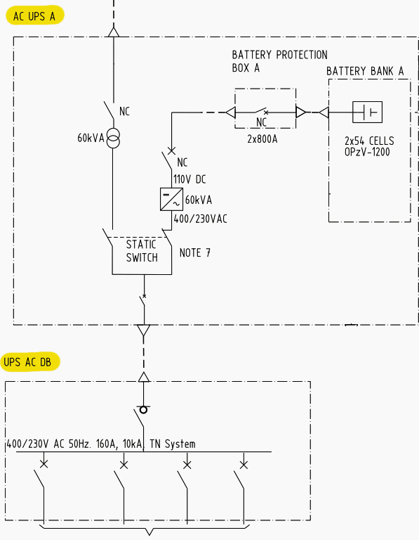
Such systems are still in wide use in industry, especially for applications such as UPS power supplies. However, the direct addition of battery power to the grid is now possible, and it opens a wide array of operational flexibility and process robustness for industry.
Figure 4 – Ellego 110 V DC UPS main circuit diagram. This is a particularly reliable and robust stand alone DC UPS system.

Figure 5 – Ellego 110 V DC UPS unit (Thyristor based DC-UPS for demanding marine and offshore applications)

3. Modern Grid Tied BESS Overview
The principle of modern BESS is heavily based on AC electrical motor drive technology. Having an understanding of such systems, and power electronics in general, will give a solid foundation to understanding modern BESS. For a deep understanding and comprehension, knowledge of control theory, Clark and Park transformations, and semiconductor switching power electronics dynamics is beneficial. But it is not necessary to have studied these topics to still obtain a useful black box system understanding of BESS.
Advancements in power electronics, control algorithms, digital signal processing speed and cost, and energy and power density of modern battery technology, has opened an emerging field of grid tied battery energy storage possibilities.
Related electrical guides & articles


Kitab Paul Shah
With a broad experience in the electrical industry, my main focus is on systems engineering. To ensure that an electrical installation functions correctly as a complete system, it is necessary to have an understanding of how each part behaves internally, how they should interact with each other, expected failure modes, and the philosophy of plant operation. Previously I have been heavily involved in marine and offshore projects, both from an engineering and design side, as well as on site installation, start up, and commissioning. This has concerned system philosophy development, procurement of electrical equipment, as well as protection design and coordination for MV and LV SWBDs, rotating machines, drives, generators, AVRs, UPS, and battery energy storage.My education is Electrical Engineering Honours degree from the University of Newcastle, Australia, focusing on power systems, control theory, and power electronics. As well as an apprenticeship and full licencing as an industrial LV and HV electrician for NSW, Australia. Additionally I hold authorisation to perform electrical work in Norway and Sweden.Profile: Kitab Paul Shah
