
CTs & VTs as Eyes and Ears
Electrical systems normally use current and voltage transformers for protection and measurement purposes. They represent the power system’s eyes and ears, and it’s essential to fully understand how they work, how to make the correct specification and most importantly, the mistakes you can make.
 What should you do not to select the wrong current and voltage transformers? (photo credit: Warna RS Sdn. Bhd.)
We’ll introduce current and voltage transformers, their categories, ratios, and metering accuracy classes and then analyze the differential protection scheme.
- Current and Voltage Transformers (CTs, VTs)
- CT and VT Polarity
- Metering Accuracy Class
- CT Relaying Accuracy Class
- Summary Notes
- BONUS! CT Theory Book and Standards IEC 600441 and IEC 61869-2 (PDF)
1. Current and Voltage Transformers (CTs, VTs)
A current transformer (CT) is a device that steps down the primary current to a lower value, usually 1 or 5 A, on the secondary winding. This reduced current can then be used with a watt-hour meter, ammeter, or protection relay. There are two categories of CTs – wound type and window type. The main conductor in a window-type configuration functions as the principal winding.
A CT 400:5 A represents the current ratio of a current transformer (CT). When a current of 400 A passes through the primary winding, a current of 5A will pass through the secondary winding.
This includes the voltage between its primary and secondary windings, as well as between its primary or secondary windings and the ground (core, case, or tank).
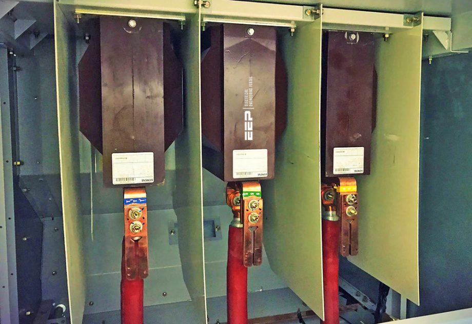
Figure 1 – Window type CTs with three different ratios

Insulation classes ranging from 600V up to Extra High Voltage (EHV) have been developed by industry standards. According to industry recommendations, the insulation class of a VT should be equal to or more than the highest line-to-line voltage present in the system at the point of connection.
As an illustration, the insulation class of a voltage transformer (VT) used on a 7200Y/12 470 V system should be a minimum of 15 kV, despite the VT having a main rating of 7200 V and being connected phase-to-ground. During a fault scenario, the voltage transformer (VT) may experience line-to-line voltage.
2. CT and VT Polarity
The correct orientation of coil winding is determined by the polarity indications on CTs and VTs, as well as the schematics. The polarities play a crucial role in ensuring the effective operation of the protective schemes. In a current transformer (CT), the current in the secondary winding flows in the opposite direction to the current in the primary winding.
This means that the currents are out of phase by 180 degrees, as shown in Figure 2.
Typically, these symbols are marked as white dots or combinations of letters and numbers. When using combinations of numbers and letters, IEEE designates H1 as the primary terminal marking and X1 as the secondary polarity indication.
Figure 2 – Polarity markings and current flows

The CT polarities should be clearly indicated on the protection diagrams in order to establish the direction of current flow that aligns with the intended operational logic. Improperly oriented window CTs installed on the primary wires will fail to trigger the differential protection system as intended. A more severe scenario might occur if one out of the six CTs is positioned in an inverted manner.
This problem is frequently encountered in the field, resulting in flawed commissioning scenarios.
Now, let’s examine the importance of the CT polarity on the functioning of a differential protection scheme. What are the consequences of incorporating a service auxiliary transformer into a differential scheme, when it is linked and draws power from within the transformer differential zone?
Let’s analyze the scheme depicted in Figure 3.
Figure 3 – Transformer differential protection

The boundary of the transformer protective zone is determined by the current transformers (CTs) located on both sides of the transformer. The problem lies in the fact that the CT1 measures a current that is 16% lower than CT2 (after accounting for the transformer ratio conversion) because of the power being used by the station service, assuming the system is operating at maximum capacity.
This is a discrepancy that could lead to the 87T triggering a trip, even while the system is operating normally. Mismatch is equal to 7.5/47 = 16%, assuming generator MVA = 40/0.85 = 47 MVA, if CT3 was not used.
Disregarding the impact of CT3 in regular operation, the opposing polarities of CT1 and CT2 result in the cancellation of currents, preventing any flow into the relay. In the event of a fault occurring within the zone, the currents combine due to their opposing directions, resulting in a substantial fault current being directed towards the relay.
A differential relay is commonly configured to trip whenever there is a discrepancy of 20-30% between two sides. Hence, the discrepancy of 16% is not enough to trigger a trip under typical operating conditions. The CT3 connection may be unnecessary for this configuration, but it is uncomfortably near. However, in this case, the scheme’s sensitivity is reduced.
It is customary to include the CT3 connector when the mismatch exceeds 5%. In order to ensure that the readings of CT1 are equivalent to those of CT2 during normal operation, the CT3 must be linked in a way that subtracts its current from the current flow from CT2.
This requires connecting the CT3 with the correct polarity positions. When CT3 is wired correctly, it eliminates the mismatch.
Suggested Course – Transformer Differential Protection Course

3. Metering Accuracy Class
Instrument transformers are categorized into different accuracy classes, with one class designated for metering purposes and another class designated for relaying purposes, as described below.
3.1 Metering Accuracy
The metering error in an instrument transformer is the result of both ratio and phase angle faults. The allowable deviation in a voltage transformer (VT), for a specified precision level, should stay consistent across the voltage range spanning from 10% below to 10% above the rated voltage.
The allowable error in a metering current transformer (CT), based on a certain accuracy class, is a single value at 100% of the rated current. At 10% of the rated current, the acceptable deviation is double that amount.
Revenue kilowatt-hour metering typically allows for an acceptable error rate of 0.3%, whereas CTs used for indicating instruments are allocated an error rate of 0.6-1%.
The metering accuracy classes specified by the IEC 61869-1 Standard for different types of measurement are 0.1, 0.2, 0.5, 1, and 3. The class classification provides an estimation of the CT’s precision. A Class 1 CT has a primary to secondary current ratio inaccuracy of 1% or less at rated current.
IEEE classifies Metering CTs into categories of 0.1, 0.3, 0.5, and 1. The data represent the percentage deviation from the rated primary current. Therefore, when a current of 100 A flows through the main, a current transformer with a 0.3 accuracy rating of 100:5 A will have a maximum error of 0.3.
A standard metering CT is commonly labeled as 0.3B0.5, with B0.5 indicating a load of 0.5 Ω.
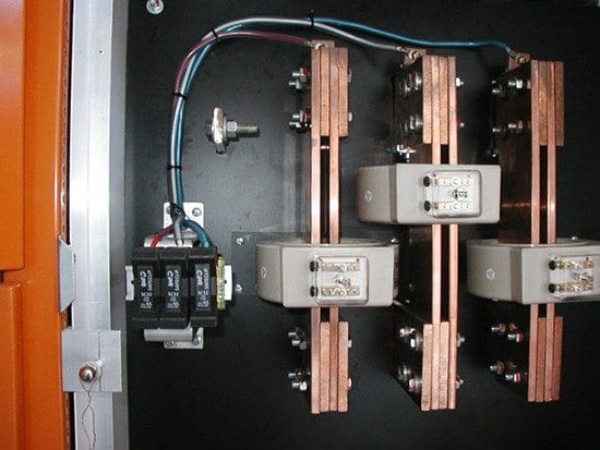
Figure 4 – Metering current transformers
3.2 Burden of CTs and VTs
The burden of a CT refers to its secondary load. The load encompasses the impedances of the CT, leads, and relays. In other words, a CT with a burden rating of B0.2 may handle an impedance of up to 0.2 Ω on the secondary circuit without compromising its accuracy within its designated classification.
If the current transformers (CTs) are situated in distant substations, the resistance of the leads can become a significant portion of the overall burden. To mitigate this issue, one can employ thicker cables and current transformers (CTs) with lower secondary currents (1 A). These measures will result in less voltage drop between the CTs and the devices they are connected to.
Table 1 shows that new digital numerical relays have much reduced burden impedances in comparison to the older electromagnetic relays.
Table 1 – Standard voltage transformer (VT) burdens
| Application | Designation | Impedance (Ω) | VA | Power factor (pf) |
| Measurements and relaying | W | 1152 | 12.5 | 0.1 |
| X | 576 | 25 | 0.7 | |
| M | 411 | 35 | 0.2 | |
| Y | 192 | 75 | 0.85 | |
| Z | 72 | 200 | 0.85 |
3.3 High Accuracy Instrument Transformers
IEEE standard C57.13.6 has provided additional accuracy classes to adapt to the transition from classic induction electromechanical devices to electronic relays and meters. As a result, manufacturers have started enhancing the precision of instrument transformers in order to utilize the reduced impedance (load) of contemporary relays and meters.
The instrument transformers now adhere to a higher accuracy requirement and also come with updated burden ratings;
- E 0.4, (1.0 VA at 5 A, unity pf),
- E 0.2, (5.0 VA at 5 A, unity pf), and
- Low current test point of 5% vs. the traditional 10% rated current, are now required.
- 0.15% accuracy instrument transformers. CTs must maintain an accuracy of 0.15% when operating at 5% of their rated current and up to the rated burden, as determined by the rating factor (RF). Levels below 5% do not guarantee accuracy.
- The accuracy of voltage transformers is 0.15% within the range of 90% to 110% of the rated voltage.
In the vicinity of 10%, or 60 amperes, accuracy cannot be guaranteed. In conclusion, a standard CT achieves less precise readings as the burden or current decreases.
You should consider the following: “What impact does it have on our revenue when our services perform significantly below that during periods of low load?“
In response to that questioning, a utility experiences revenue loss during periods of insufficient demand. The utilization of high-precision, extended-range current transformers that meet or surpass the 0.15S standard is thus advantageous for a utility.
This results in a “extended range” for the CT. By employing a conventional high accuracy ratio of 600:5, a utility could potentially attain an expanded metering range of 1200 amperes to 6 amperes (with a rating factor of 2).
Figure 5 – High accuracy current transformers

When a utility is operating in a “variable load” installation, a high-precision CT is most efficient during periods of low demand. This would be the case in a factory with two or three shifts, where the capacity is reduced during the second or third shift. A church with a reduced staff during the week but a more substantial workload on Sunday mornings and Wednesday evenings due to the presence of larger congregations is another illustration.
An independent study conducted by a major municipal utility determined that, depending on the load characteristics at the installation, a CT with a high degree of accuracy could generate between 0.2% and 0.8% more revenue.
4. CT Relaying Accuracy Class
This applies to current transformers (CTs) that are used to trigger relays for the purpose of control and protection. The current transformer (CT) needs to have the capacity to withstand high primary currents and transform them into lower values that are appropriate for the relay’s application, while maintaining a decent level of accuracy. A common method of classifying relay accuracy is by using the designations C100 or T100.
The letter “C” represents calculated correctness, while the letter “T” represents tested accuracy.
The number indicates the maximum secondary voltage that can be generated at the secondary terminals without reaching saturation, when the current is 20 times the nominal value and the allowable burden is at its nominal level.
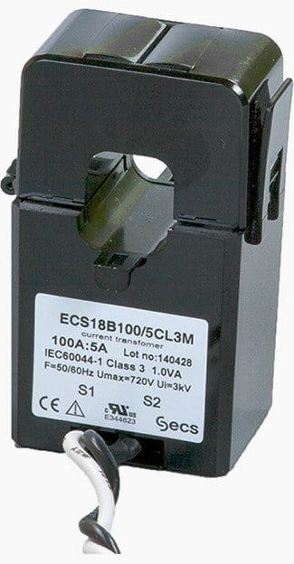
Figure 6 – Window-type cable current transformer
The relay classification 10C200 signifies that it has an accuracy of 10% when operating at 20 times the nominal primary current and with a secondary impedance. Therefore, this current transformer (CT) would have an error margin of no more than 10% when subjected to a secondary current 20 times greater than the normal value, with a secondary burden of 2.0 Ω
(20 × 5 A × 2 Ω = 200 V).
Frequently, the CT ratios and burdens are erroneously chosen on switchgear or metering devices and relaying devices that are connected to the same set of CTs.
Allow us to provide an illustration: The motor control center (MCC) has a load current of 150 A and operates at a voltage of 575 V. The fault level of the MCC is 50 kA. The current transformer (CT) ratio selected is 200:5 A, with a temperature rating of 10C50.
Figure 7 – MCC single-line diagram with marked CTs and VTs positions

The exposure of the CT to the maximum fault current is 250 times greater than the ratio of 50,000 divided by 200, resulting in a value of 20. Based on the current load, these current transformers (CTs) are expected to reach saturation during a failure at around 4 kA and would not synchronize with the other relays.
If the current transformers (CTs) are configured for immediate disconnection, set at 12 times the nominal current (In) of 1800 A, the CTs will function correctly as long as the increase in burden voltage is limited to less than 50 V.
Following that, the CT will begin to reach saturation. P represents the protection class of the CT. The predicted impedance for a 15 VA burden and 5 A secondary current transformer (CT) is determined as demonstrated below. Increasing the impedance would necessitate a corresponding increase in the VA burden.
- VA = 52 × Z;
- Z = VA/52
- Z = 15 VA/25
- Z = 0.6 Ω protective circuit impedance.
Download Tool – Current transformer (CT) saturation calculator
4.1 Continuous Thermal Rating Factor (RF)
The RF, or Ratio Factor, pertains to Current Transformers (CTs) and is a numerical value that indicates the maximum increase in the primary load current above the CT’s specified rating, without surpassing the permissible temperature rise of the CT. This is a specification indicating the CT’s capacity to handle excessive loads.
The CT manufacturer’s literature commonly states that the CT has a rating of 2.0 at an ambient temperature of 30 °C, and an RF rating of 1.5 at an ambient temperature of 55 °C.
These assertions indicate that the CT can operate continuously at twice its nameplate rating in a 30 °C environment, and at 1.5 times its nameplate rating in a 55 °C environment. It is important to understand that a fault current will greatly surpass the nominal current of the current transformer (CT) multiple times before the equipment is tripped.
Good Reading – Selection of relay for incoming & outgoing feeders for MV/LV MCC switchgear
Selection of relay for incoming and outgoing feeders for MV and LV MCC switchgear
4.2 Multiratio CTs (Multiple Ratio Taps)
CTs can occasionally be provided with multiple ratio taps. As an example, current transformers (CT) in high voltage (HV) bushings can be designed with ratings of 400/800/1200-5 A, belonging to the C class and designated as 10C400. This CT has the capability to function at any of those taps.
The burden classification is determined based on the highest tap. For this scenario, the values are 1200 A and 400 V, and they are adjusted proportionally to the lower ratios.
Figure 8 – Multi-ratio current transformer

4.3 Connections of CTs and VTs
Connecting the instruments for power metering has become straightforward with the introduction of new digital meters. The system typically consists of three current transformers (CTs) and three voltage transformers (VTs) as the input, along with digital communication ports for remote indications. The meter, with its software algorithm, generates all the measurements, such as A, V, W, Wh, pf, Demand, etc., in a digital format.
No other requirements are necessary. It is advisable to have an extra analog voltmeter installed on each switchgear and MCC incoming feeder. This allows for a rapid assessment of the operational status of the assembly.
Table 2 – Standard CT burdens
| Application | Designation | Impedance (Ω) | VA | Power factor (pf) | Volts on CT secondary (winding) |
| Measurements | B0.1 | 0.1 | 2.5 | 0.9 | C10 |
| B0.2 | 0.2 | 5 | 0.9 | C20 | |
| B0.5 | 0.5 | 12.5 | 0.2 | C50 | |
| B0.9 | 0.9 | 22.5 | 0.9 | ||
| Relaying | B1 | 1 | 25 | 0.5 | C100 |
| B2 | 2 | 50 | 0.5 | C200 | |
| B4 | 4 | 100 | 0.5 | C400 | |
| B8 | 8 | 200 | 0.5 | C800 |
Voltage transformers (VTs) are often interconnected in a Y configuration for three-phase VTs, with one phase connected to ground, or in a V configuration for two VTs, with one phase connected to another phase (see to Table 2).
C100 = 20 × 5 A × B = 20 × 5 × 1 = 100 V, at 20 times nominal current.
where, C100 is CT relaying class, B is burden in Ω.
Thus, this current transformer (CT) can handle a load of 20 × 5 A with a resistance of 1 Ω in order to fulfill its designated class. If the burden is increased, the current transformer (CT) will not be able to satisfy its specified accuracy class at that particular current level.
5. Summary Notes
So, let’s make some summary notes. It’s important to make sure to always choose current transformers (CTs) with the desired accuracy class and appropriate ratios to meet the required metering range.
According to the American National Standards Institute (ANSI), use current transformers (CTs) for relaying purposes that have the necessary accuracy class. Ensure that the ratios of these CTs are within 1/20 of the estimated fault current to prevent saturation. Reduce the load in order to expand the operational capacity prior to reaching saturation.
Regarding the IEC standards, it’s similar to ANSI, but take into account that the accuracy class before to saturation for IEC designations is one-tenth of the fault current.
6. BONUS! CT Theory and and Standards IEC 600441 and IEC 61869-2 (PDF)
Download CT Theory and Standards IEC 600441 and and IEC 61869-2 (PDF) (for premium members only):
References:
- Practical Power Plant Engineering by Z. Bedalov
- Network protection and automation guide by (ex) Alstom Grid, now General Electric
- Core-balance current transformer by Loreme
- Electric Power Substations Engineering By James C. Burke
Related electrical guides & articles


Edvard Csanyi
Hi, I'm an electrical engineer, programmer and founder of EEP - Electrical Engineering Portal. I worked twelve years at Schneider Electric in the position of technical support for low- and medium-voltage projects and the design of busbar trunking systems.I'm highly specialized in the design of LV/MV switchgear and low-voltage, high-power busbar trunking (<6300A) in substations, commercial buildings and industry facilities. I'm also a professional in AutoCAD programming.
Profile: Edvard Csanyi

Best website for all engineers
This is nice article and very educative