
Checking switchgear and electrical room
What is safe when it comes to an older electrical equipment and internal-arc flash in electrical room. Substation operators generally assume that with the covers and doors closed, the switchgear is in a totally safe work condition. This technical article explores the differences in switchgear with respect to internal arc flash and how this affects the safety of the substation operator.

 Are your switchgear and electrical room safe?
We’ll also discuss the safety of electrical rooms and the early signs that, if not properly detected and addressed promptly, can cause significant damage and injuries to the substation personnel and equipment.
- Infrared Thermography
- Why You MUST Recognize the Fault Type? (Bolted Fault or Arcing Fault)
- How Does This Affect the Switchgear? (Why arc faults do not simply happen)
- Is Your Installed Switchgear Arc-resistant?
- How Shall We Proceed?
- To Conclude…
- What You MUST Check in the Electrical Room?
- Attachment (PDF) 🔗 Download ‘Handbook for Performing Arc-Flash Hazard Calculations’
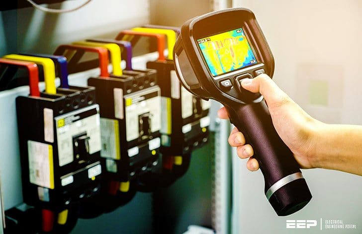
1. Infrared Thermography
Infrared thermography of electrical switchgear is a well-known and accepted predictive maintenance technique. Working with any kind of live, electrical equipment incorporates an element of risk, but how does this risk manifest itself in relation to arc-flash and infrared thermography?
So, the question is, is our electrical switchgear totally safe?
2. Why You MUST Recognize the Fault Type?
Bolted Fault or Arcing Fault?
Today, the infrared community talks a great deal about “arc fault” or “arc flash,” but to understand what an arc fault actually is and how it affects switchgear, one must first appreciate the difference between an arc fault and another, albeit less common, occurrence known as a “bolted fault”.
A bolted fault is basically a dead short via a highly conductive medium between two different phases or between a phase and Earth conductor.
Figures 1 and 2 show an example of a bolted fault situation. Since the fault current is confined to the relevant conductor, there is usually no energy release outside of the system’s conductive path.
This fault type, however rarely, is utilized for protective device selection due to its tendency to produce the highest short-circuit current values.
Figure 1 – Bolted three phase short circuit fault

Bolted line-to-line faults, as depicted in Figure 2, are more prevalent than three-phase faults and exhibit fault currents that are roughly 87% of the three-phase bolted fault current.
This fault type is unbalanced over the three phases, and its fault current is rarely computed for equipment ratings as it does not yield the highest fault current magnitude.
The line-to-line current can be determined by multiplying the three-phase value by 0.866, provided that the impedances Z1 and Z2 are equal.
Figure 2 – Bolted Line-To-Line Faults

As is commonly known, an arcing fault is very dangerous and, as we shall see quite different from a bolted fault. An arcing fault is also a short circuit between phases or between phase and Earth, but this time the short circuit current flows through the air, rather than through an actual conducting material such copper.
When an arc fault occurs, temperatures at the fault location increase instantly to over 2760°C (the melting point of copper is 1084°F).
Figures 3 and 4 show Line-to-line-to-ground faults and Line-to-ground faults. Under are fault conditions, a huge amount of damage is caused to the equipment, and a significant injury hazard is posed to any personnel in the vicinity at the time of the fault.
Line-to-line-to-ground faults, as depicted in Figure 3 are generally line-to-ground faults that have progressed to involve a second phase conductor. This is an asymmetrical fault. The magnitudes of double line-to-ground fault currents typically exceed those of line-to-line faults, although are inferior to those of three-phase faults.
The computation of double line-to-ground fault currents necessitates the application of symmetrical components analysis. The impedance of the ground return channel will influence the outcome and should be measured if feasible.
Figure 3 – Line-To-Line-To-Ground Fault (or Double Line-Ground Fault)

Line-to-ground faults, as seen in Figure 4, are the most prevalent kind of failures and often cause minimal disruption to the system. The current in the faulted phase may vary from nearly zero to a value marginally exceeding the typical three-phase fault current.
The size of the line-to-ground fault current is dictated by the grounding method of the system and the impedance of the ground return path for the fault current.
The determination of precise line-to-ground fault current magnitudes necessitates the specialized calculation methods of symmetrical components.
Figure 4 – Line-To-Ground Short Circuit Fault

Are faults are usually caused by one of the following dynamic interventions into an otherwise static system:
- Dropped tools
- Induced airflow
- Dielectric breakdown of insulation
- Mechanical failure
So, now that we understand the difference between the two fault ocurrences, we can look at the switchgear design in relation to them.
Watch Video – Arc Resistance and its impact on the Relay operation
3. How Does This Affect The Switchgear?
Why arc faults do not simply happen?
Traditionally, switchgear was designed, tested, and rated to withstand the bolted fault current level that could occur, as this is always higher than the arc fault level, due to the lower current impedance of the cross phase conduct in comparison to air.
The switchgear was designed to such an extent that the bolted fault current did not exceed the maximum current-carrying capacity of the conductors, and as such, the equipment was not damaged due to the fault.
How we have seen, there is a vast difference between the effects of a bolted fault and an arc fault, and a successful bolted fault type test does not mean that for switchgem can subsequently withstand an are fault – even at a lower short circuit current level – which is much more violent.
Figure 5 – Arc-flash incident in the low voltage switchgear

Today, arc-resistant switchgear undergo arc fault type tests in order to satisfy the market that the equipment is indeed safe, should either fault occur at the tested energy level or less.
Note that it is not correct to associate arc-flash danger solely with voltage. Energy = Voltage × Current × Time. So, it is quite possible for the are flash energy level on 480V equipment to be as high as or higher than on 4160V or 15kV equipment.
In order to maintain the arc-resistant protection of the switchgear during operation, all doors and covers most be closed and latched or bolted, while energized.
Figure 6 – Arc-Resistant Switchgear

4. Is Your Installed Switchgear Arc-resistant?
It’s hard to say, but the straight answer is most probably no. Arc-resistant switchgear is expensive due to its construction and certification requirements and, as such, this type of equipment is in the minority in today’s workplace.
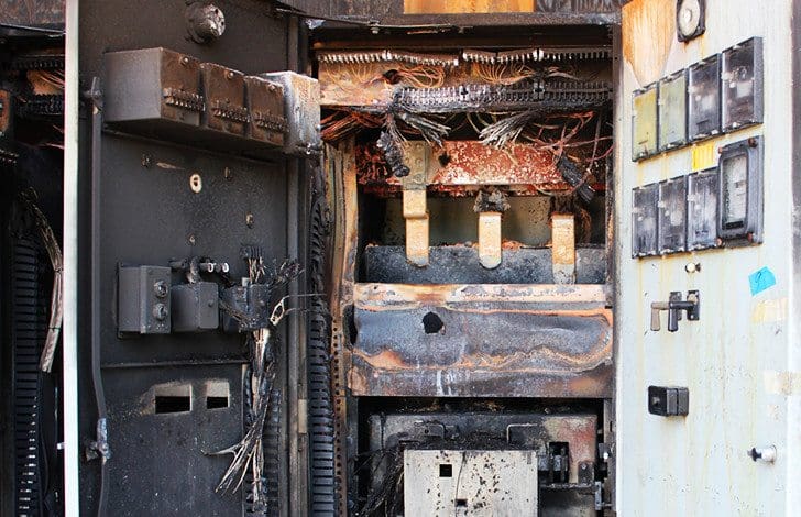
It is a recognized fact that should a fault occur in a non-arc-resistant switchgear, then not only will the equipment be destroyed beyond repair, but it is normal for such explosions to cause covers/doors to become forcibly detached from the equipment.
Figure 4 shows the result of the fault explosion in a low-voltage cubicle. This is the image that every electrical thermographer must have in their mind BEFORE entering a live, operating switch room.
Just because the covers are closed does NOT mean you are safe.
Figure 7 – Destroyed low voltage switchboard due to the arc flash
5. How Shall We Proceed?
There are a number of points the infrared thermographer needs to remember when dealing with potential arc fault occurrences:
- Arc faults do not simply happen. They are the result of a change in the static nature of the switchgear.
- If possible, check the operating schedule of the equipment you will be surveying. If a fault is to occur other than from human intervention, then it is likely to happen when a circuit closes and/or load increases.
- Ensure that predictive maintenance is carried out regularly to reduce the potential for mechanical failure.
- Do NOT remove covers or doors to perform the infrared inspection, as this is more likely to cause an arc fault than prevent one.
Further Study – Switchgear interlocking system and arc protection that you MUST consider in the design
Switchgear interlocking system and arc protection that you MUST consider in the design
6. To conclude…
With run-to-failure being an unacceptable option, electrical infrared thermography must continue. Howevar, it must be executed in a manner that is as safe as possible, and operators performing the inspections must be trained to understand the dangers and risks associated with the work.
Ultimately, live electrical equipment is extremely dangerous, regardless of whether the covers are removed or not. It is important that the infrared thermography operators not become indifferent about the safety requiremems needed to carry out on such equipment.
However, care needs to be taken when applying such standards to your facility. This manuscript has shown that:
- We dare not assume that, if covers are in place, the operator is totally safe. This needs to be addressed in the facility’ss infrared inspection procedures.
- Low-voltage systems can have higher incident energy than medium-voltage systems and, as such, it is not sufficient to distinguish between such systems, safety-wise, on voltage alone.
- In order to reduce the potential for are fault, we must continue with infrared thermography, but in a manner that does NOT contribute to such a fault ocurring.
Suggested Course – MV Switchgear Schematics Course: Tripping, Trip Circuit Supervision, Interlocking and Indication Circuits
7. What You MUST Check in the Electrical Room?
Check #1
Any strange smells in electrical rooms should be investigated right away. It typically indicates that there is excessive heat being generated in one of the panels. When insulation becomes excessively heated, it emits a distinct and noticeable odor.
Check #2
To ensure that main disconnect switches and circuit breakers remain in optimal working condition, it is advisable to exercise them on an annual basis.
Check #3
Transformers should be checked to insure air intake grills are clean and that there are no objects stored around the transformers that can block the cooling air supply.
Transformers generate heat and this heat must be removed or the insulation will break down causing eventual failure of the transformer.
Check #4
Access to all electrical rooms must be controlled, allowing entry only to supervised and maintenance personnel, or other individuals with proper authorization.
Figure 8 – Maintenance substation personel checking th switchgear

Check #5
Storage should not be permitted in electrical rooms. Stored material will limit access to the panels in case of an emergency and could hinder airflow to the transformers.
Storing materials outside of designated areas will also deter unauthorized access.
Check #6
When inspecting electrical rooms, one can place a hand on the different circuit breaker and switch panels. If any components feel warm to the touch, it indicates a potential overheating issue that requires immediate attention.
Figure 9 – Checking low-voltage circuit breakers with infrared thermography
Check #7
Any atypical noises coming from transformers or electrical switchgear require thorough investigation.
Check #8
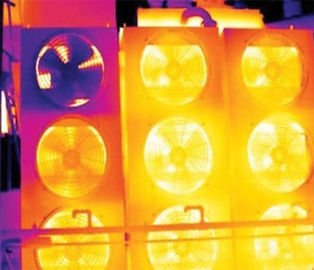
Rooms housing transformers are typically equipped with ventilation systems to dissipate the heat produced by these devices. Poor ventilation can lead to elevated ambient temperatures in the power rooms, potentially resulting in transformer overheating.
Figure 10 – An infrared picture of fans temperature increase
Other Checks
Additional factors to evaluate when inspecting panels and transformers within the preventative maintenance framework include:
- Thermographic scanning of the switchgear and transformers, particularly in larger facilities that receive 600V three-phase power.
- Panels and switchgear in smaller facilities (schools, stores, etc.) could be inspected annually by a qualified professional. This involves accessing the panels, inspecting for any signs of overheating, and ensuring that cable connections are securely tightened.
The issue could originate from a loose connection at the fuse holder within the disconnect switch. The expenses for the repairs can be significant cost, resulting in a two-day closure of the store.
Further study – Do you know what an arc flash is? If not, keep reading, it’s important.
Do you know what an arc flash is? If not, keep reading, it’s important.
8. Attachment (PDF): Handbook for Performing Arc-Flash Hazard Calculations
Download: Handbook for Performing Arc-Flash Hazard Calculations (for premium members only):
References:
- EEE Recommended Practice for Calculating Short-Circuit Currents in Industrial and Commercial Power Systems
- Switchgear safety – Tony Holliday
- Power romms – Royal & SunAlliance, Engineering Insurance & Loss Control Services
Related electrical guides & articles


Edvard Csanyi
Hi, I'm an electrical engineer, programmer and founder of EEP - Electrical Engineering Portal. I worked twelve years at Schneider Electric in the position of technical support for low- and medium-voltage projects and the design of busbar trunking systems.I'm highly specialized in the design of LV/MV switchgear and low-voltage, high-power busbar trunking (<6300A) in substations, commercial buildings and industry facilities. I'm also a professional in AutoCAD programming.
Profile: Edvard Csanyi

Very useful information. Thank you.
You’re welcome, Gnanavel. I’m glad you find this article useful.